00196044-05 - sg x und x4i fse_en.pdf - 第211页
Gantry Reference Run Sequence at X and Y Axis (A 364) Gantry Reference Run (with A364) S tudent Guide (FSE) SIPL ACE X Series and X4I Edition 01/2009 EN Gantry 21 1 6.1.1.1 Description The head mounting plate with the pl…
Gantry
Overview Mechanical Structure of X and Y Axes
Student Guide (FSE) SIPLACE X Series and X4I
Gantry Edition 01/2009 EN
210
6.1.1 Mechanical Structure of X and Y Axes
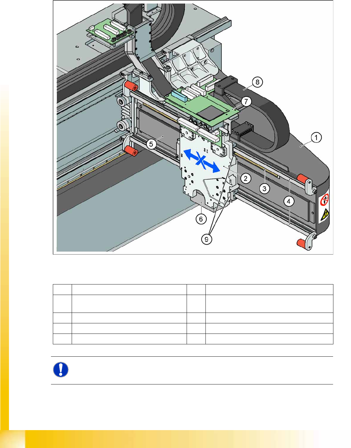
Please Note: X and Y Axes have the same basic mechanical parts.
6-2: Mechanical structure "Gantry"
Legend
1 X gantry made of carbon fiber 6 PCB camera mounted under the gantry
2 Head mounting plate with integrated primary
part of X axis linear motor
7 Boards (head interface with Vision board below -
vertical - the head adapter board)
3 Incremental scale 8 X trailing cable
4 Linear guidances for X axis (above/below) 9 Temperature sensors
5 Secondary part X axis (magnet)
NOTE:
To improve placement accuracy, the temperature sensors compensate the offset between the
PCB camera and the nozzle, based on the temperature of the head mounting plate.
Gantry
Reference Run Sequence at X and Y Axis (A364) Gantry Reference Run (with A364)
Student Guide (FSE) SIPLACE X Series and X4I
Edition 01/2009 EN Gantry
211
6.1.1.1 Description
The head mounting plate with the placement head is moved in the X direction by the linear guidances,
which are mounted above and below the secondary part of the linear motor. The Y axis moves the entire
X axis gantry with the placement head.
For X and Y axis position recognition we use incremental metal scales. These are positioned above the
secondary part for the X axis and below the secondary part of the Y axis. An incremental encoder reads
the increments, which are then sent to the axis controller boards, for determination of the axis positions
and for motor control.
Each X and Y axis has a rubber bumper as hardware stop at its ends.
6.2 Gantry Reference Run (with A364)
6.2.1 Reference Run Sequence at X and Y Axis (A364)
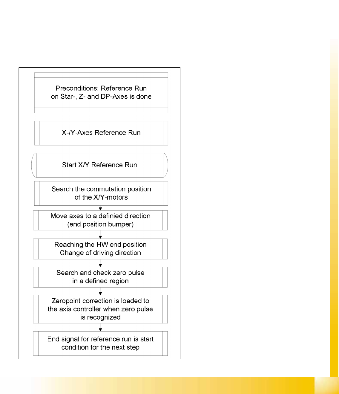
6-3: Reference run sequence
After the commutation search, the motor is in an
undefined position for the control system. When
referencing with bumper recognition (hardware
end stops), the axis moves successively against
the bumpers. For this purpose, fixed target values
are set by the axis controller, which are
increasingly nearer to the mechanical end stop.
After a certain time, this approach function
reaches a state in which the set target position is
no longer reached (actual position ≠ target
position, the axis is at the hardware end stop
(bumper)).
After a certain time (approx. 10 ms) and after
reaching a certain motor current, the direction of
travel is reversed and the axis searches for the
zero pulse within a specified range. This zero
pulse must be found within a predefined travel
range. If the zero pulse has been found in this
area, further zero pulses will be searched for in an
area of approx. 2.5 mm
After reaching and checking the zero pulse, the
axis is in a defined position.
The reference run for the main axes is started
simultaneously at all 4 gantries.
Gantry
Gantry Reference Run (with A364) Searching for the X and Y Commutation Position (A364)
Student Guide (FSE) SIPLACE X Series and X4I
Gantry Edition 01/2009 EN
212
6.2.2 Searching for the X and Y Commutation Position (A364)
A commutation position search for the 3 phases AC-drives on the gantry starts right after the head axes
reference run is succesfully finished.
1. Commutation position search during initial reference run:
Preconditions and function:
Axis reference run must be successfully completed at the relevant placement heads.
2 motor phases are switched to the power supply of the servo amplifier.
The 3-phase AC motor moves to the next suitable magnetic position.
2 other motor phases are switched to the servo power supply and the axis moves further.
These switching steps are repeated multiple times.
The axis reference run is continued with a reference position search for the position measuring system.
6.2.3 Reference Run at X and Y Axis (A364)
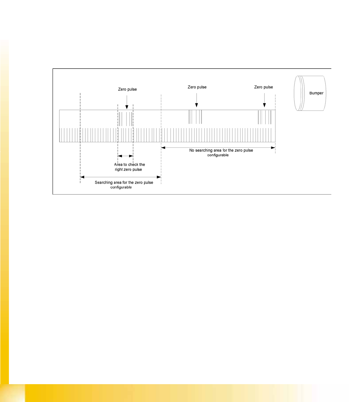
6-4: Zero pulse
Description of zero pulse search:
Requirements:
– The commutation point search has been completed.
– The motor is in position control.
1. After the hardware end stop has been reached and the axis has moved in the opposite direction, the
search for a zero pulse is prohibited within a certain distance of the bumper (approx. 25 mm).
2. After moving out of this prohibited area, the search begins. If the zero pulse is found in this area,
further pulses will be searched for in an area of approx. 2.5 mm If only one zero pulse is found, an
end position message is issued and the reference run is completed.
In the event of a fault, multiple zero pulses or no zero pulses may occur in the defined area. In this
case, the axis will stop and an error message with be issued.
3. The axes are now in a defined position. After finding and checking the zero pulse, the zero point
correction is loaded.
4. The reference run for the main axes has now been completed. The vacuum and height reference
runs will begin.