00196044-05 - sg x und x4i fse_en.pdf - 第206页
Energy and Compressed Air Supply Pneumatic System Cooling the X Axis Motor s S tudent Guide (FSE) SI PL ACE X Series and X4I Energy and Compres sed Air Supply Edition 01/20 09 EN 206 5.3.14 Cooling the X Axis Motors 5.3.…
Energy and Compressed Air Supply
Compressed Air Supply CPP Pneumatic System
Student Guide (FSE) SIPLACE X Series and X4I
Edition 01/2009 EN Energy and Compressed Air Supply
205
5.3.12 Compressed Air Supply CPP
5.3.13 Compressed Air Distribution Twin Head
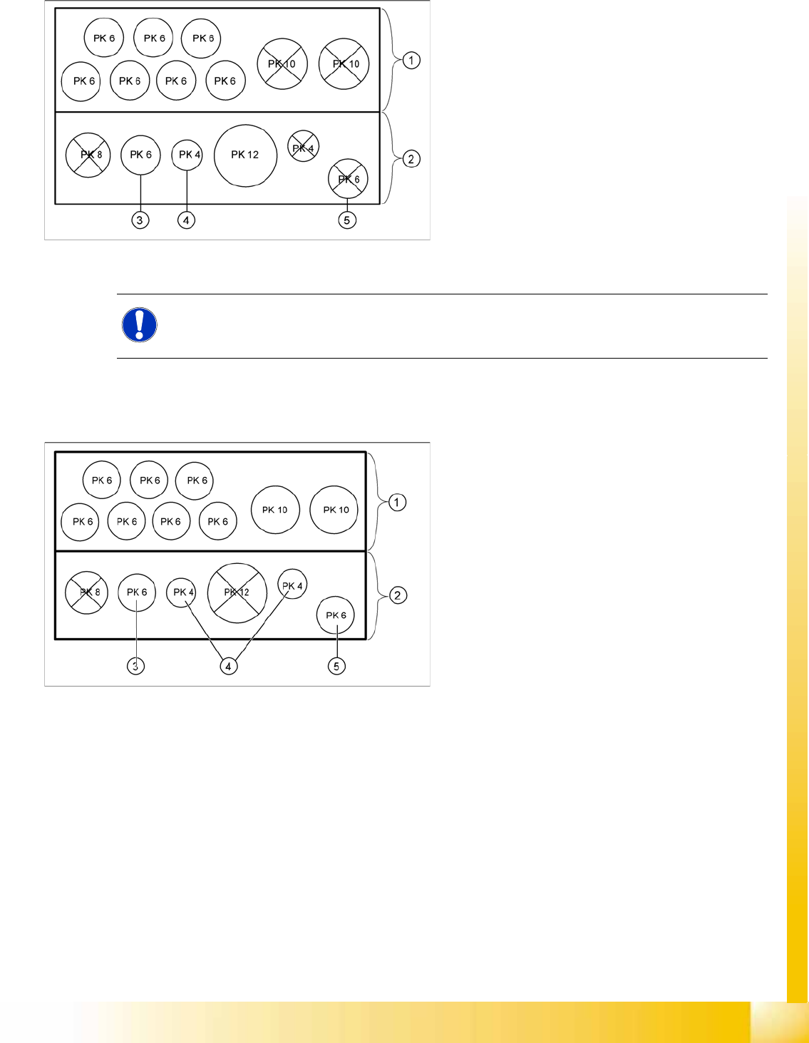
Legend
1. Rear view of the pneumatic distributor
Input:
- 7 fold pneumatic hose (PK 6)
- 2 fold pneumatic hose
- Optional vacuum pump (PK 10)
2. Front view of the pneumatic distributor
Output:
- CPP head
3. Hold circuit
4. Return cylinder
5. Pressure Control Valve
NOTE:
With the introduction of the "Fast head exchange", the return unit and the pressure control valve
are supplied via a PK6 connection from the pneumatic distributor.
5-33: Pneumatic distributor for trailing cable CFK06/
Legend
1. Rear view of the pneumatic distributor
Input:
- 7 fold pneumatic hose (PK6)
- 2 fold pneumatic hose (PK10)
2. Front view of the pneumatic distributor
Output:
- Twin Head
3. Pressure control valve segment 1
4. Return cylinder segment 1 and 2
5. Pressure control valve segment 2
Energy and Compressed Air Supply
Pneumatic System Cooling the X Axis Motors
Student Guide (FSE) SIPLACE X Series and X4I
Energy and Compressed Air Supply Edition 01/2009 EN
206
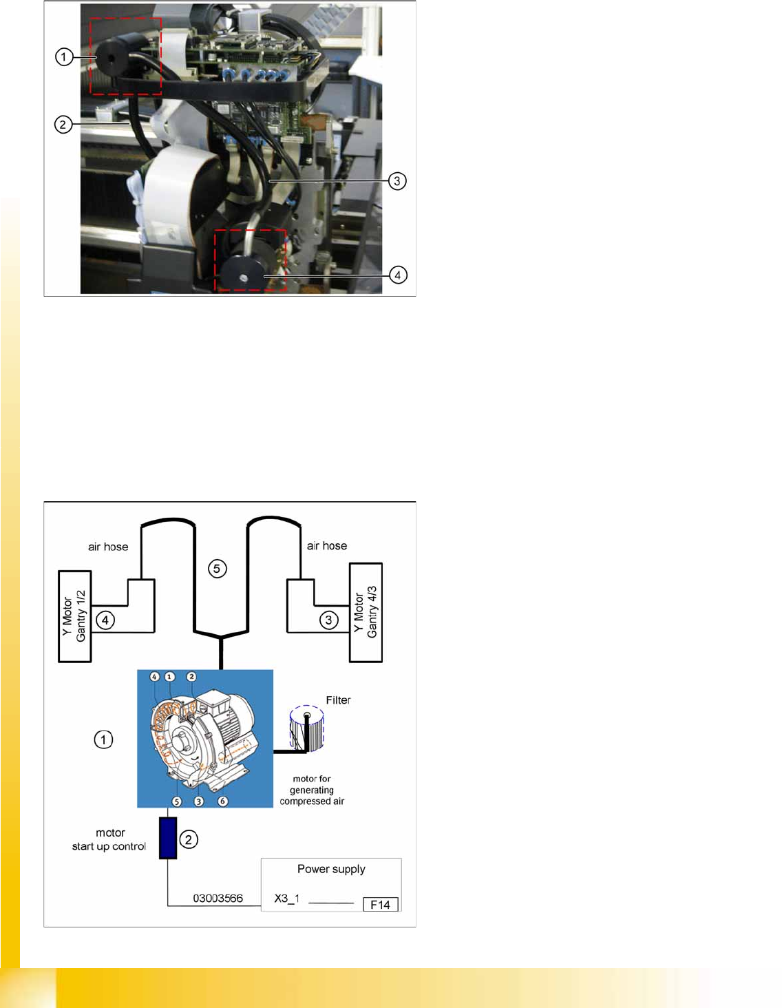
5.3.14 Cooling the X Axis Motors
5.3.15 Cooling the Y Axis Motors for Placement Area 1/2
To cool the Y axis motors, an additional pneumatic system is integrated, which sucks the air from the
environment, compresses it in a compressor and conducts its through a hose system to each of the Y
axis motors.
The motor coil temperature is monitored. If this exceeds 110°C, a message will appear on your screen.
This simple cooling system is installed to ensure that the Y axis does not overheat.
5-34: Cooling system X axis motor
The exhaust air from the vacuum generator
(pressure control valve) of the C&P head is used
to cool the X axis motors.
Legend
1. Air distributor
2. Air tube for cooling the X axis
3. Hose via the distributor to the pneumatic unit
4. Silencer
5-35: Cooling system Y axis motor
Legend:
1. Compressor, located in main unit
2. Startup control for the compressor
3. Y axis motor gantry 4/3
4. Y axis motor gantry 1/2
5. air hose for air supply used for cooling the
linear motor

Energy and Compressed Air Supply
Cooling the Y Axis Motors for Placement Area 1/2 Room for Your Sketches and Notes
Student Guide (FSE) SIPLACE X Series and X4I
Edition 01/2009 EN Energy and Compressed Air Supply
207
5.4 Room for Your Sketches and Notes