00196044-05 - sg x und x4i fse_en.pdf - 第395页
Twin Head Axis Control of Twin Head Z Axis Axis Control S tudent Guide (FSE) SIPL ACE X Series and X4I Edition 01/2009 EN T win Head 395 Twin head - view of Z axis with 10 N placement force (downwards) Legend Twin head -…
Twin Head
Axis Control Axis Control of Twin Head Z Axis
Student Guide (FSE) SIPLACE X Series and X4I
Twin Head Edition 01/2009 EN
394
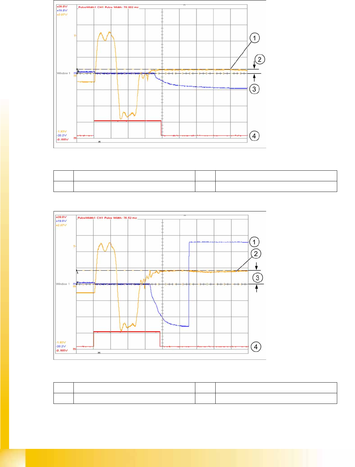
Twin head - view of Z axis with 2 N placement force (downwards)
Legend
Twin head - view of Z axis with 5 N placement force (downwards)
Legend
1 Torque-forming motor current 500 mV/20 ms 3 Position deviation 5 V/20 ms
2 Amplitude approx. 200 mV 4 Positioning time approx. 78 ms
1 Position deviation 5 V/20 ms 3 Amplitude approx. 500 mV
2 Torque-forming motor current 500 mV/20 ms 4 Positioning time approx. 78 ms
Twin Head
Axis Control of Twin Head Z Axis Axis Control
Student Guide (FSE) SIPLACE X Series and X4I
Edition 01/2009 EN Twin Head
395
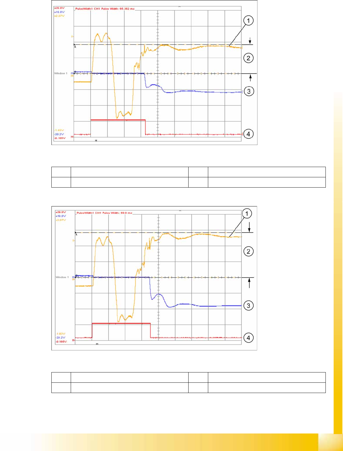
Twin head - view of Z axis with 10 N placement force (downwards)
Legend
Twin head - view of Z axis with 15 N placement force (downwards)
Legend
1 Torque-forming motor current 500 mV/20 ms 3 Position deviation 5 V/20 ms
2 Amplitude approx. 1000 mV 4 Positioning time approx. 65 ms
1 Torque-forming motor current 500 mV/20 ms 3 Position deviation 5 V/20 ms
2 Amplitude approx. 1500 mV 4 Positioning time approx. 70 ms
Twin Head
Axis Control Axis Control Twin Head D-Axis
Student Guide (FSE) SIPLACE X Series and X4I
Twin Head Edition 01/2009 EN
396
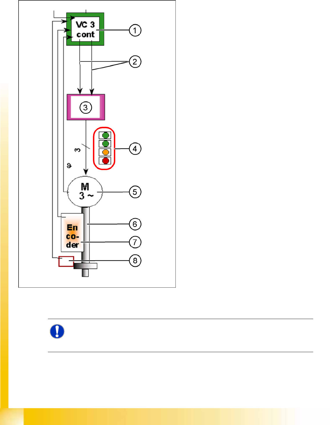
9.6.5 Axis Control Twin Head D-Axis
9.6.5.1 Checking the Twin Head D-Axis Dynamics
The D-axis is driven by a 2-phase AC motor, fed
from 60 V DC voltage. Axis control is via 2 control
signals from the VC3 controller (phase shift 90°) I
nom "W" and I nom "U".
Legend
1. Axis controller board A363 with VC3 controller
(VC = Velocity Commutation) or A 364
2. Control signals
3. Servo amplifier
4. LEDs on servo board:
– Power supply ON
– Servo enable, if the enable signal has
been received from the axis board.
– Display R.M.S. current limiter shorter than
2.5 s.
– Error: Overvoltage, overcurrent,
overtemperature or nominal current
overshoot longer than 2.5 sec.
5. 2 phase AC motor.
6. Between the motor and the incremental
encoder there is a fixed mechanical
connection.
7. Incremental encoder: transmits the exact
position of the axis (track signals).
The servo board controls the AC motor directly.
NOTE:
The positioning times between the left and right turns of the sleeve may deviate from one
another considerably. However, the time characteristic of this axis is not critical for Twin head
operation, due to the placement procedure.