00196044-05 - sg x und x4i fse_en.pdf - 第51页
Overview SIPLACE X and X4I Configuration Options SIPLACE X Series S tudent Guide (FSE) SIPL ACE X Series and X4I Edition 01/2009 EN Overview 51 3.1.1.1 Placement Principle The placem ent system is based on a tor sionally…
Overview
SIPLACE X Series SIPLACE X and X4I Configuration Options
Student Guide (FSE) SIPLACE X Series and X4I
Overview Edition 01/2009 EN
50
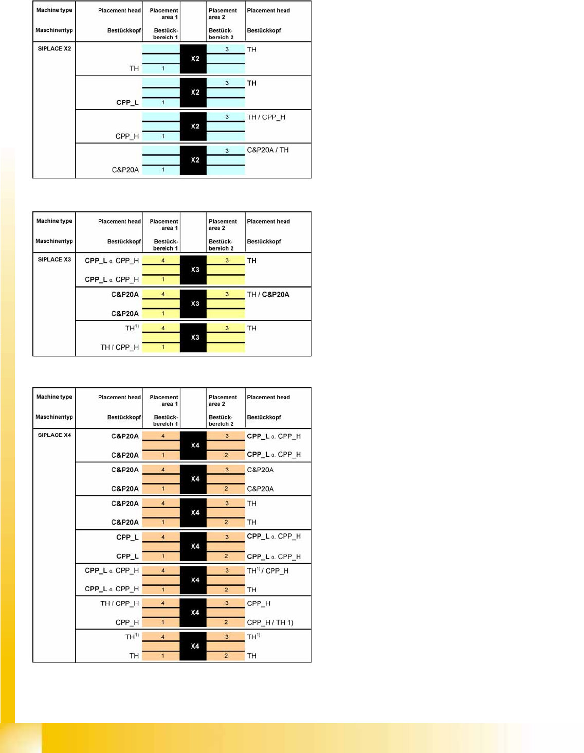
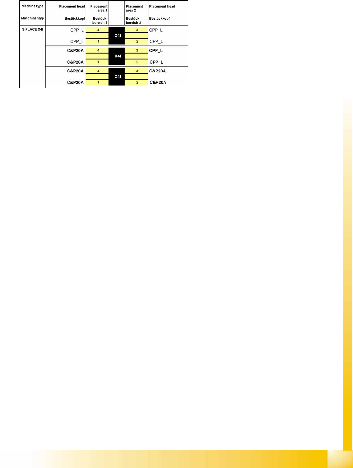
3.1.1 SIPLACE X and X4I Configuration Options
Legend
Placement heads
– TH = Twin head
– CPP_L = Collect&Pick&Place head in low
assembly position
– CPP_H = Collect&Pick&Place head in
high assembly position
– C&P20A = Collect&Place head with 20
segments
– Bold = Standard head configuration
1/2/3/4 = Gantry 1/2/3/4
1)
: The TH/TH combination in one PA was
introduced with SW 603 and may only be used
with the stationary cameras with VLT33. This
also applies to CPP / CPP or CPP / TH
combinations. Retrofitting kits have been
defined to upgrade machines already in
operation.
Overview
SIPLACE X and X4I Configuration Options SIPLACE X Series
Student Guide (FSE) SIPLACE X Series and X4I
Edition 01/2009 EN Overview
51
3.1.1.1 Placement Principle
The placement system is based on a torsionally rigid and vibration dampened machine frame made of
cast steel. The placement system has either two (X2), three (X3) or four (X4) gantries. These can be
positioned independently of one another in the X and Y directions, by fast and accurate linear motors.
Each gantry is equipped with a placement head.
Two placement head variants are used:
The Collect&Place procedure for components from size 01005 to fine pitch with a CPP head with 12
segments or with a C&P20A head with 20 segments.
The Pick&Place procedure with one Twin head for fine pitch/super fine pitch components
The head modularity principle developed by Siemens allows you to change placement heads quickly and
easily.
Four locations are available for supplying the components. A maximum of four component trolleys or two
Matrix Tray Changers (MTC) can be used.
The station software 70x supports the C&P20A, CPP, TH and high force TH placement heads with X
feeders. A combination of S feeders and DLM heads is not possible!
Depending on the machine type, one or two gantries are operated in placement area 1 (gantries 1/4) and
placement area 2 (gantries 2/3), each with one placement head.
This picks up the components from the feeders which are on a stationary component trolley.
There are two methods of component placement:
Alternating mode with a dual conveyor, dual conveyor as single conveyor or a single conveyor.
This placement mode is the mode known for X series machines: One gantry picks up components,
while the other gantry places components. In each placement area, a board is placed alternately by
both placement heads.
In I-Placement mode with a dual conveyor or quad lane conveyor.
In this placement mode, both gantries in a particular placement area place independently of one
another. Each gantry places a certain board on its own conveyor lane (1 or 2 ). I Placement mode is
possible without synchronization up to a board width of 76.5 mm. Boards with widths up to 180 mm
require gantry synchronization, although placement is still performed independently for each lane.
This means that two boards can be placed at the same time on a single conveyor, one in PA1 and the
other in PA 2. When using a dual conveyor, four boards can be placed at the same time and when using
a quad lane conveyor, this is increased to an impressive eight boards at the same time.
3-2: SIPLACE X4I - Configuration
Overview
SIPLACE X Series Configurations
Student Guide (FSE) SIPLACE X Series and X4I
Overview Edition 01/2009 EN
52
3.1.2 Configurations
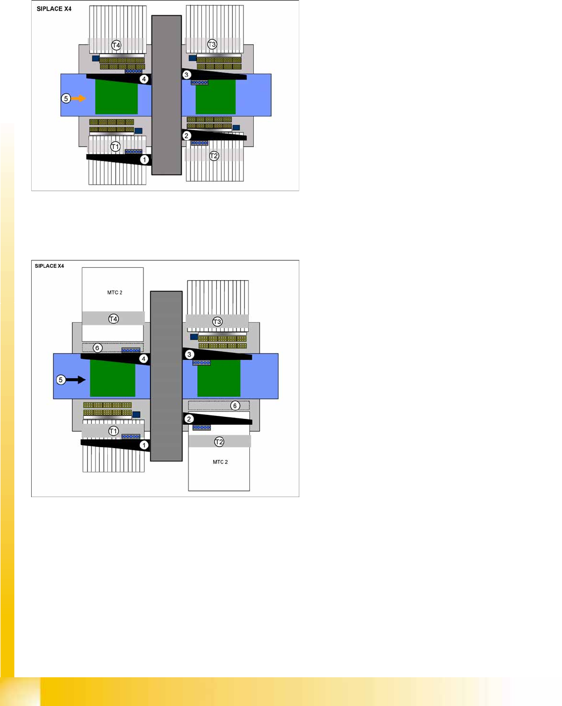
3.1.2.1 SIPLACE X4 Configuration
3.1.2.2 SIPLACE X4 with MTC2 - Configuration
3-3: SIPLACE X4 configuration options
Legend
Dimensions (L x W) 2.38 x 2.75 m
1-4: Gantry 1 - 4 with CPP, C&P20A or Twin
Head
T1 - T4: Locations 1 - 4, 40 tracks for 8 mm X
feeder
5: Direction of transport , PCB conveyor with 5
areas
Restriction: When configuring the head, always
take into account the maximum component height
for the placement head concerned.
3-4: SIPLACE X4 configuration options
Legend
Dimensions (L x W) 2.38 x 3.70 m
1-4: Gantry 1 - 4 with CPP, C&P20A or Twin
Head
T1 - T4: Locations 1 - 4
40 tracks for 8 mm X feeder,
Locations 2 and 4 for changeover table or
MTC2
5: Direction of transport , PCB conveyor with 5
areas
6: Room for stationary cameras
Restriction: When configuring the head, always
take into account the maximum component height
for the placement head concerned.