00196044-05 - sg x und x4i fse_en.pdf - 第324页
Collect, Pick and Place Head (CPP) Pickup and Placement Cycle for CPP Placement Modes S tudent Guide (FSE) SI PL ACE X Series and X4I Collect, Pick and Place Head (CPP) Edition 01/2 009 EN 324 8.4.2.1 Collect&Place M…
Collect, Pick and Place Head (CPP)
Working Position on Placement Head Pickup and Placement Cycle for CPP
Student Guide (FSE) SIPLACE X Series and X4I
Edition 01/2009 EN Collect, Pick and Place Head (CPP)
323
8.4 Pickup and Placement Cycle for CPP
8.4.1 Working Position on Placement Head
8.4.2 Placement Modes
The CPP head functions according to the Collect&Place principle, whereby additional operating modes
(Pick&Place and mixed mode) are possible to help extend the component spectrum.
The placement mode is, on the one hand, dependent on the configured camera and, on the other hand,
on the component dimensions and their tolerances in SIPLACE Pro.
The respective placement mode is determined by the Optimizer in SIPLACE Pro band can not be
influenced.
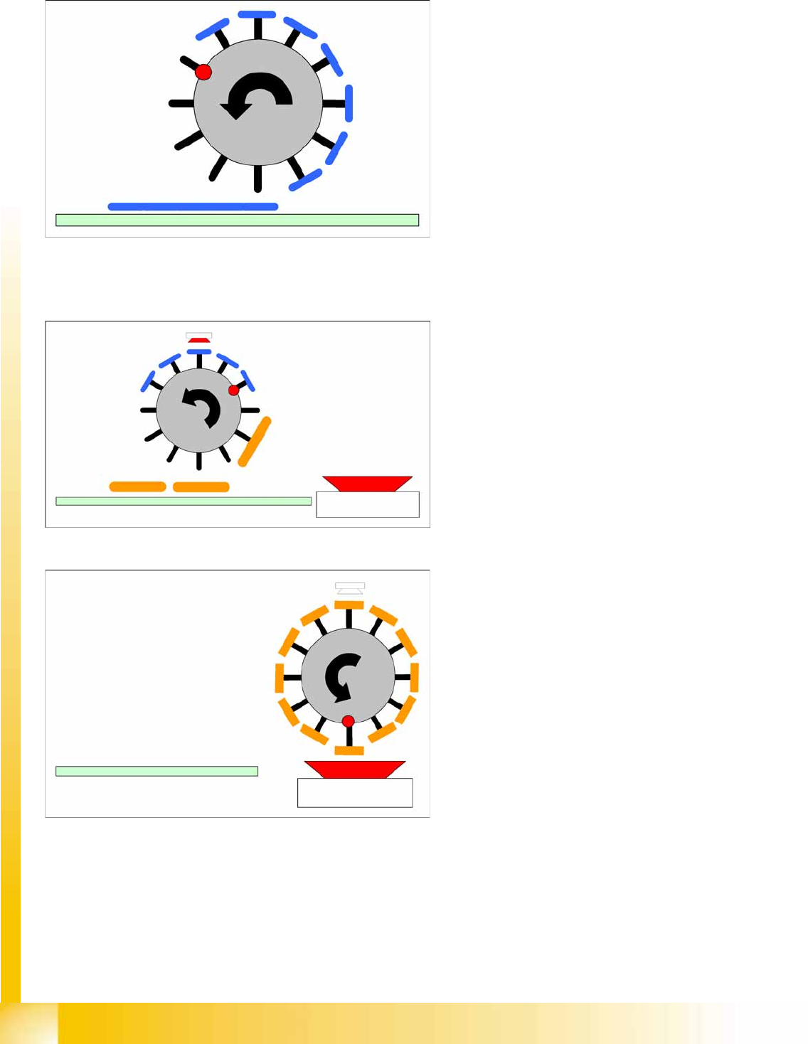
C&P mode: The Collect-and-Place mode is the same mode for the C&P6/12 and C&P20A placement
heads. Components are picked up (the quantity depends on the number of segments), optically centered
with the component camera and then placed.
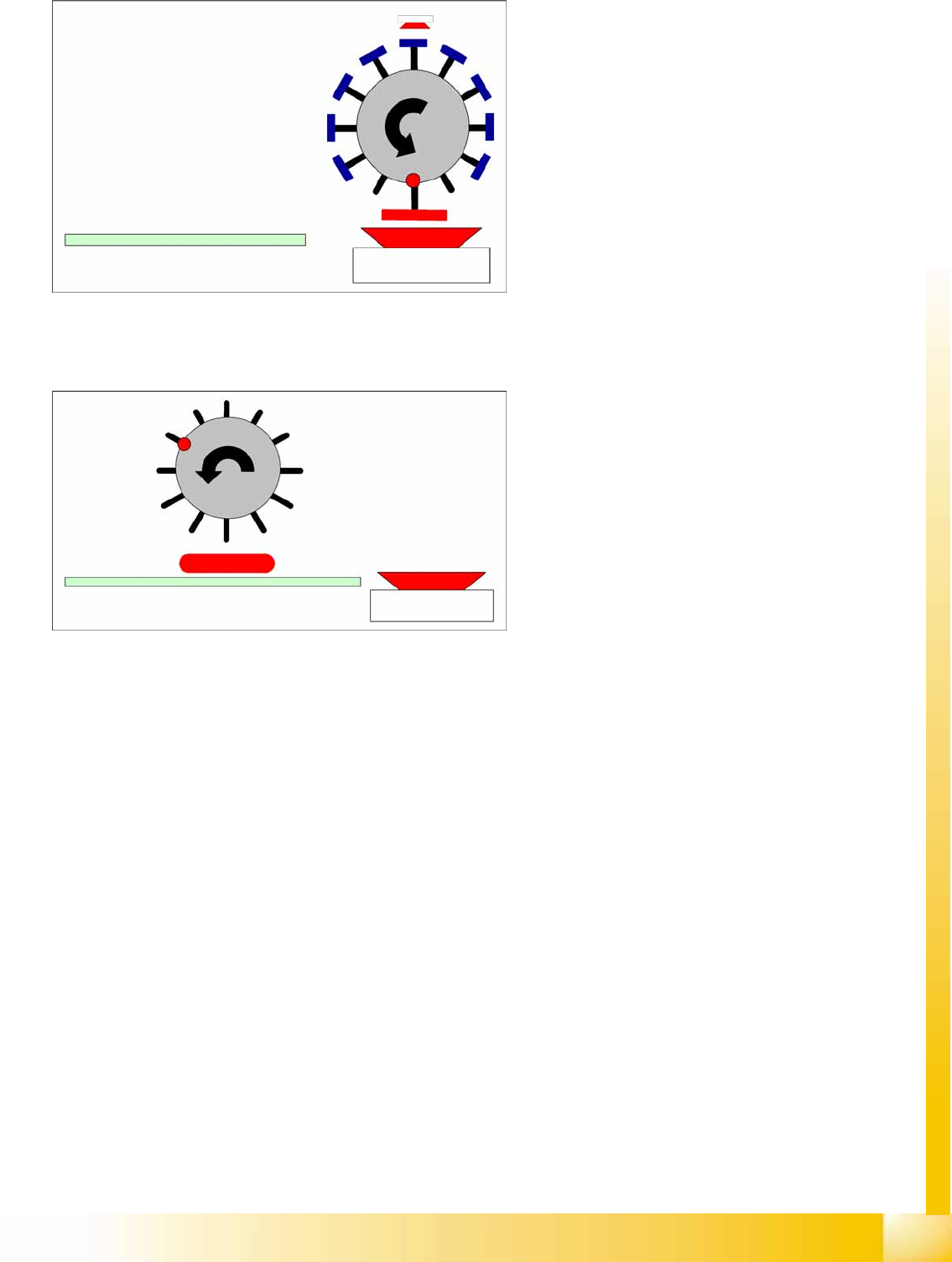
P&P mode: The Pick-and-Place mode is the mode used for IC and TwinHead. It is therefore also used
for the CPP head, which picks up components with either one or more segments, according to the
component size. Due to their size, it is not possible to rotate these components with the head and they
need to be optically centered via the stationary camera and then placed.
Mixed mode: Mixed mode differentiates between the following two cases:
The components are small enough to be rotated by the head.
The components are too large. Just 2 or 3 components are picked up, centered by the stationary
camera and then placed.
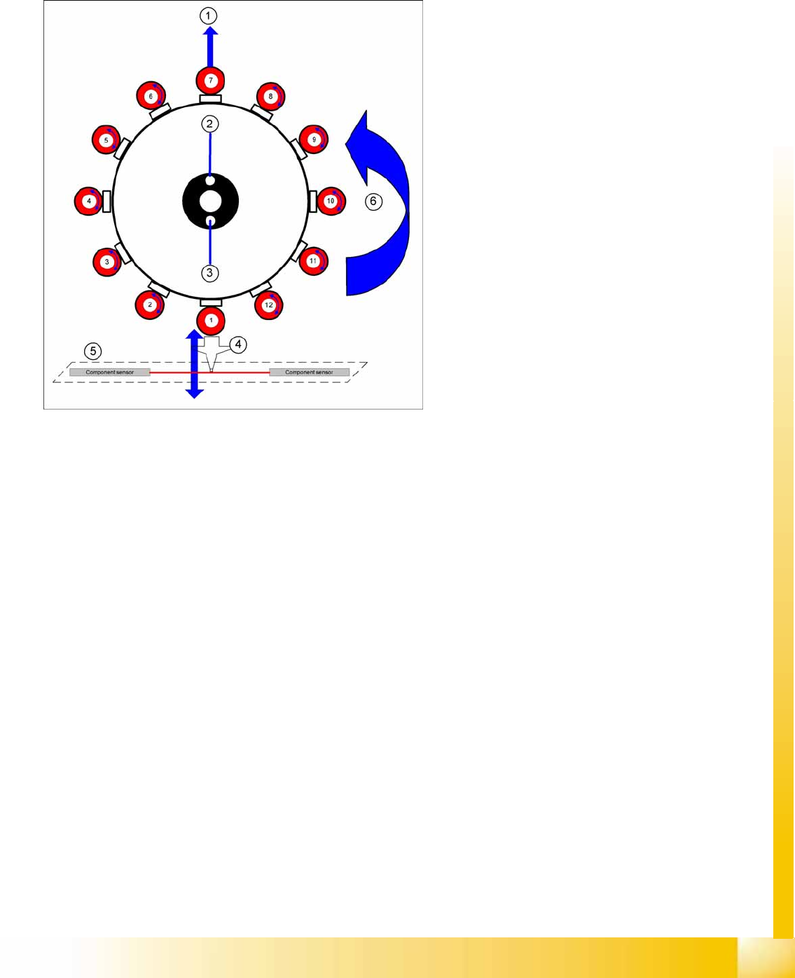
8-8: Working Position on Placement Head
Legend
1. Optical centering (component camera)
2. Vacuum measurement hold circuit
3. Vacuum measurement placement circuit
4. Pickup/placement station and reject position
5. Position of component sensor
6. Direction of processing in C&P mode
Collect, Pick and Place Head (CPP)
Pickup and Placement Cycle for CPP Placement Modes
Student Guide (FSE) SIPLACE X Series and X4I
Collect, Pick and Place Head (CPP) Edition 01/2009 EN
324
8.4.2.1 Collect&Place Mode
8.4.2.2 Mixed Mode
Component spectrum:
01005 to 27x27 mm
8.5 mm high
Speed:
20,000 to 24,000 CO/h
Accuracy:
+/- 50 µm (4 sigma)
0.3° (4 sigma)
Mixed mode 1
Component spectrum:
01005 to 32x32 mm
11.5 mm height
Accuracy:
+/- 45 μm (4 sigma) with stationary camera
Mixed mode 2
Component spectrum: 01005-32x32mm,
11.5 mm height
Accuracy:
+/- 45 μm (4 sigma) with stationary camera
Collect, Pick and Place Head (CPP)
Placement Modes Pickup and Placement Cycle for CPP
Student Guide (FSE) SIPLACE X Series and X4I
Edition 01/2009 EN Collect, Pick and Place Head (CPP)
325
8.4.2.3 Pick&Place Mode
Mixed mode 3
Component spectrum:
01005 to 32x32 mm,
11.5 mm height
Accuracy:
+/- 45 μm (4 sigma) with stationary camera
Component spectrum:
01005 to 50x40 mm
11.5 mm height
Speed:
Up to 1.500 cph
Accuracy:
+/- 40 µm (4 sigma)
0.1° (4 sigma)