00196044-05 - sg x und x4i fse_en.pdf - 第228页
Gantry Axis Control Axis Control Assemblies S tudent Guide (FSE) SI PL ACE X Series and X4I Gantry Edition 01/2009 EN 228 6.5 Axis Control 6.5.1 Axis Control Assemblies 6.5.2 Checking the X Axis Dynamics The inspection o…
Gantry
Checking the Track Signals Track Signals and Zero Pulse
Student Guide (FSE) SIPLACE X Series and X4I
Edition 01/2009 EN Gantry
227
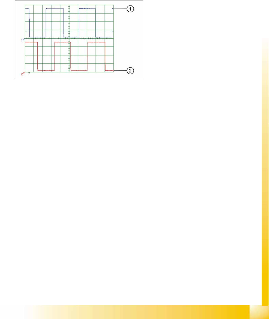
6.4.2.2 Digital Track Signals
To check the digital track signals, connect the track signal tester and the oscilloscope. (see Section
(6.4.1.2 Measuring the Digital Zero Pulse Signal
J
224 ) )
The measurement sequence is identical to that described in Section (6.4.2.1 Analog Track Signals
J
226 ) .
6-19: Digital track signals 90° phase shift
Legend
1. Track A
2. Track B
Gantry
Axis Control Axis Control Assemblies
Student Guide (FSE) SIPLACE X Series and X4I
Gantry Edition 01/2009 EN
228
6.5 Axis Control
6.5.1 Axis Control Assemblies
6.5.2 Checking the X Axis Dynamics
The inspection of dynamics occurs with the following signals:
Deviation of position
Uncommutated target current value
End signal (adapter board, axis in target position)
Actual position = target position signal (axis test box output end position signal)
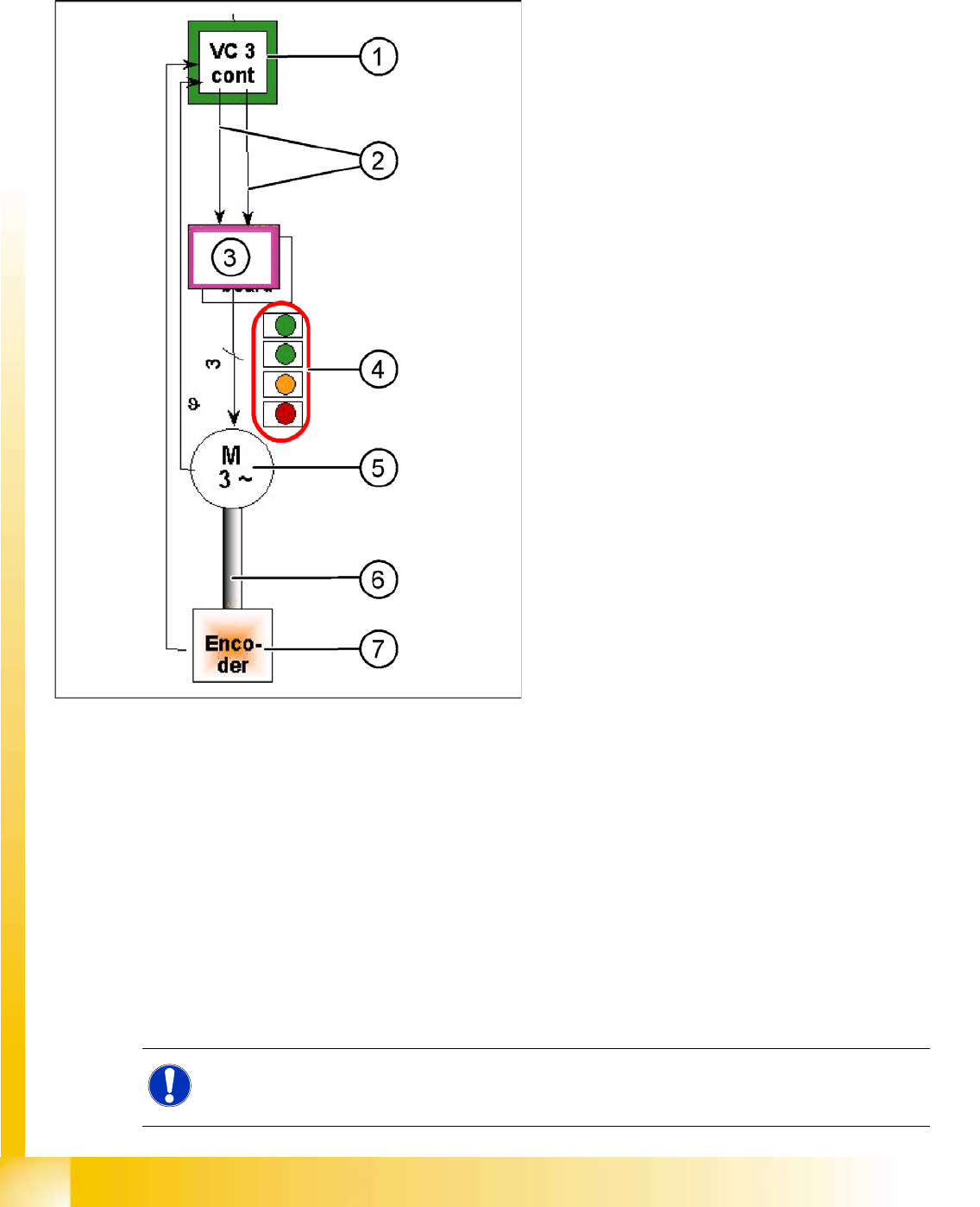
6-20: "Axis control" assemblies
The control loop for the X and Y axis consists of
the following parts:
Axis card A363 with VC3 controller or A364
Servo board (TDS)
3 phase AC linear motor
Measurement system (incremental scale and
encoder (read unit))
To protect the linear motors from overtemperature,
all these motors have an internal temperature
sensor.
Legend
1. Axis controller board A363 with VC3 controller
(VC = Velocity Commutation) or A 364
2. Control signals I
nom "W"
and I
nom "U"
3. Servo amplifier
4. LEDs on servo board:
GREEN: power supply ON
GREEN: Servo enable, if the enable signal
has been received from the axis board.
ORANGE: Display R.M.S. current limiter
shorter than 2.5 s.
RED: Error: overvoltage, overcurrent,
overtemperature longer than 2.5 sec.
5. 3-phase AC linear motor for X and Y axes with
integrated temperature sensor.
6. Between the motor and incremental encoder
there is a fixed mechanical connection.
7. Incremental encoder: transmits the exact
position of the axis. The track signals are the
only feedback signals for the axis control.
The servo board directly controls the linear motor,
the intermediate circuit voltage is 250 V.
NOTE:
Before checking the axis dynamics, make sure that the machine has reached its operating
temperature. Switch the machine on at least 30 minutes before you begin work.
Gantry
Checking the X Axis Dynamics Axis Control
Student Guide (FSE) SIPLACE X Series and X4I
Edition 01/2009 EN Gantry
229
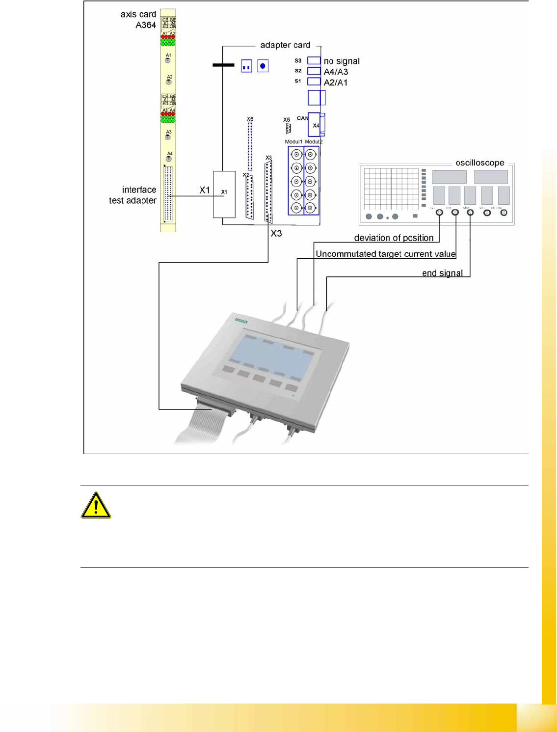
6.5.2.1 Measurement Setup with SAT Box and A364
6-21: Measurement setup with SAT box
ATTENTION:
When checking the dynamics, it may be sufficient if you check the travel times and overshoot
behavior of the axis with the SIPLACE axis tester (SAT) display and the values in the settings
tables.
However, when checking for errors, you will need to use a suitable oscilloscope for the dynamics
analysis.