00196044-05 - sg x und x4i fse_en.pdf - 第91页
Overview Conveyor System Overview of Components S tudent Guide (FSE) SIPL ACE X Series and X4I Edition 01/2009 EN Overview 91 3.2.12.2 Single Conveyor Construction The single conveyor system consists of an input conveyor…

Overview
Overview of Components Conveyor System
Student Guide (FSE) SIPLACE X Series and X4I
Overview Edition 01/2009 EN
90
Board stopper
In the placement area, the board is stopped by the laser light barrier. This laser light barrier recognizes
the front edge of the board and stops it. This prevents the board from hitting the mechanical end stopper.
The positioning accuracy for the board is +/-0.5 mm.
An optional second, mechanical stopper is available for long boards, with lengths up to 610 mm.
Lifting table
Each placement area has one or two independently working lifting tables (single/dual conveyor). The
lifting table is driven indirectly via a pneumatic cylinder, with 5/2 direction control valve. Different PCB
thicknesses are automatically compensated. The vertical guidance for the lifting table plate (up/down) is
defined at four points. The travel distance is determined by a measurement system.
The top position is controlled by the measurement system, with the help of an incremental encoder and
a defined time window. The conveyor motor checks whether the board has been successfully clamped
into place.
The bottom position is checked by a measuring system, a proximity switch on the pneumatic cylinder
and a defined time window.
The space below the board is 40 mm.
The dual conveyor can also be used as a single conveyor, if the conveyor sides from lane 2 are moved
together (flexible dual conveyor).
NOTE:
The 74 mm high board supports (red socket) can no longer be used on the SIPLACE HF and X
series machines.
Overview
Conveyor System Overview of Components
Student Guide (FSE) SIPLACE X Series and X4I
Edition 01/2009 EN Overview
91
3.2.12.2 Single Conveyor Construction
The single conveyor system consists of an input conveyor, two placement areas, the intermediate
conveyor and the output conveyor. Each conveyor has automatic width adjustment and two lifting tables
to clamp the PCB in place (not for the SIPLACE X4I).
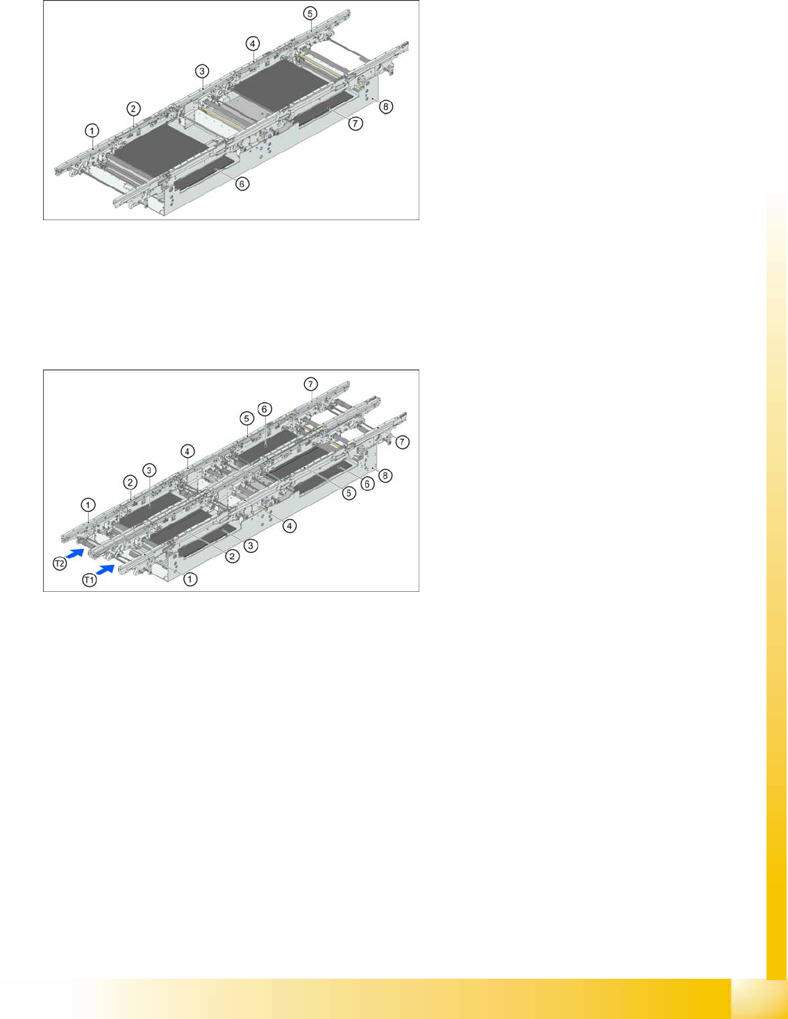
3.2.12.3 Dual Conveyor Construction
The dual conveyor has two conveyor lanes (1 and 2). In the standard model, the fixed conveyor side is
on the right side of each lane. This fixed conveyor side can be easily changed to the left.
3-31: Board conveyor construction
Legend
1. Input belt
2. Processing conveyor 1
3. Intermediate belt
4. Processing conveyor 2
5. Output belt
6. Lifting table 1
7. Lifting table 2
8. Mounting frame
3-32: Dual Conveyor Construction
Legend
1. Input belt
2. Processing conveyor 1
3. Lifting table 1
4. Intermediate belt
5. Processing conveyor 2
6. Lifting table 2
7. Output belt
8. Mounting frame
Overview
Overview of Components Conveyor System
Student Guide (FSE) SIPLACE X Series and X4I
Overview Edition 01/2009 EN
92
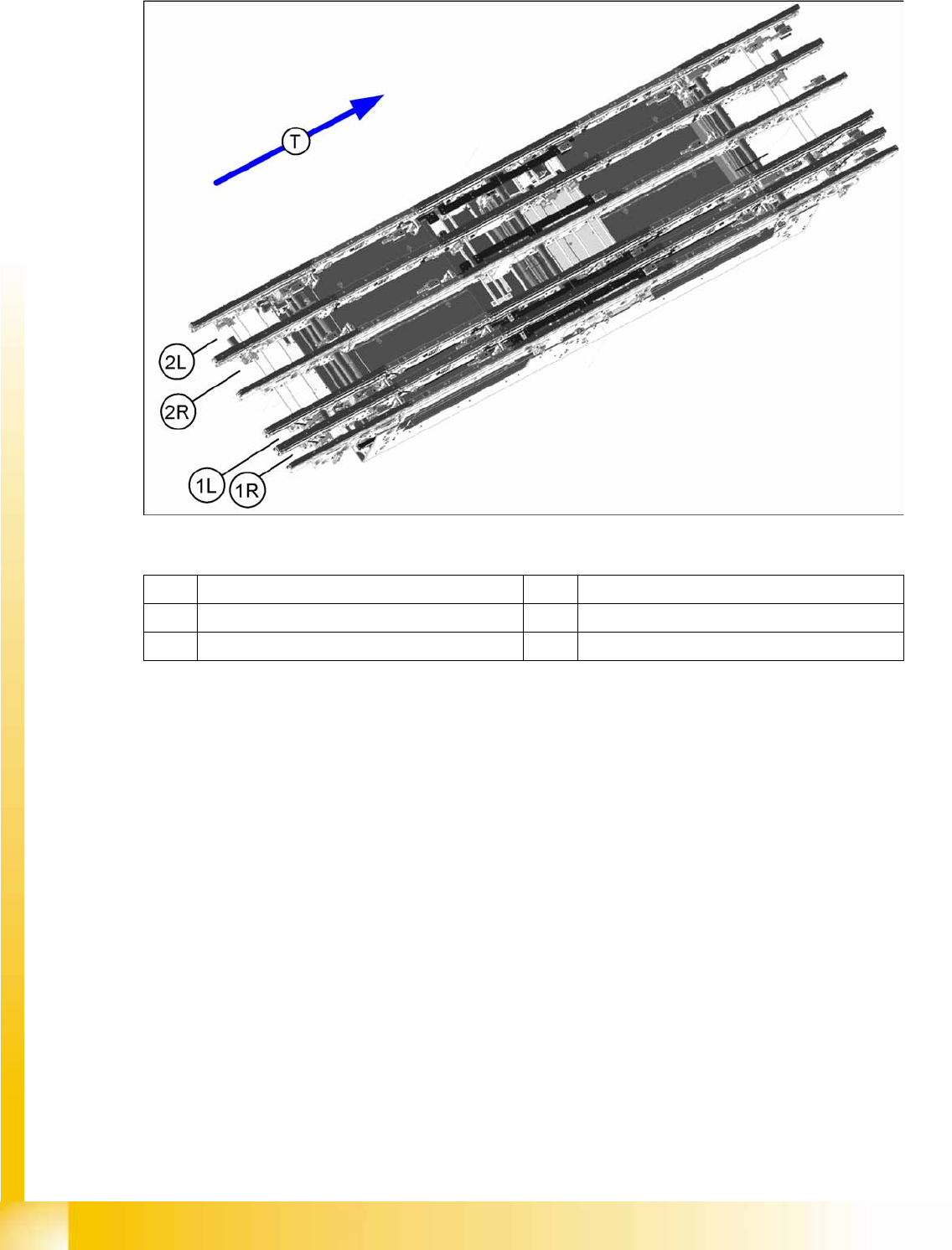
3.2.12.4 Quad Lane Conveyor Construction
Legend
The quad lane conveyor has 4 lanes. Conveyor lane 1 is divided into lanes 1L and 1R while conveyor
lane 2 is divided into lanes 2L and 2R.
This conveyor option allows you to produce a complete product with top and bottom sides on the same
conveyor lane. At the same time, another complete product can be produced on the second main lane.
(1R) Conveyor lane 1 right (1L) Conveyor lane 1 left
(2R) Conveyor lane 2 right (2L) Conveyor lane 2 left
(T) Transport direction