00196044-05 - sg x und x4i fse_en.pdf - 第516页
Head Modularity Head Modularity Production requirements S tudent Guide (FSE) SI PL ACE X Series and X4I Head Modularity Edition 01/2 009 EN 520 13.3 Head Modularity 13.3.1 Production requirements Which decisions must be …

Head Modularity
Placement Principle SIPLACE X and X4I Configuration Options
Student Guide (FSE) SIPLACE X Series and X4I
Edition 01/2009 EN Head Modularity
519
13.2.1 Placement Principle
The placement system is based on a torsionally rigid and vibration dampened machine frame made of
cast steel. The placement system has either two (X2), three (X3) or four (X4) gantries. These can be
positioned independently of one another in the X and Y directions, by fast and accurate linear motors.
Each gantry is equipped with a placement head.
Two placement head variants are used:
The Collect&Place procedure for components from size 01005 to fine pitch with a CPP head with 12
segments or with a C&P20A head with 20 segments.
The Pick&Place procedure with one Twin head for fine pitch/super fine pitch components
The head modularity principle developed by Siemens allows you to change placement heads quickly and
easily.
Four locations are available for supplying the components. A maximum of four component trolleys or two
Matrix Tray Changers (MTC) can be used.
The station software 70x supports the C&P20A, CPP, TH and high force TH placement heads with X
feeders. A combination of S feeders and DLM heads is not possible!
Depending on the machine type, one or two gantries are operated in placement area 1 (gantries 1/4) and
placement area 2 (gantries 2/3), each with one placement head.
This picks up the components from the feeders which are on a stationary component trolley.
There are two methods of component placement:
Alternating mode with a dual conveyor, dual conveyor as single conveyor or a single conveyor.
This placement mode is the mode known for X series machines: One gantry picks up components,
while the other gantry places components. In each placement area, a board is placed alternately by
both placement heads.
In I-Placement mode with a dual conveyor or quad lane conveyor.
In this placement mode, both gantries in a particular placement area place independently of one
another. Each gantry places a certain board on its own conveyor lane (1 or 2 ). I Placement mode is
possible without synchronization up to a board width of 76.5 mm. Boards with widths up to 180 mm
require gantry synchronization, although placement is still performed independently for each lane.
This means that two boards can be placed at the same time on a single conveyor, one in PA1 and the
other in PA 2. When using a dual conveyor, four boards can be placed at the same time and when using
a quad lane conveyor, this is increased to an impressive eight boards at the same time.
13-1: SIPLACE X4I - Configuration
Head Modularity
Head Modularity Production requirements
Student Guide (FSE) SIPLACE X Series and X4I
Head Modularity Edition 01/2009 EN
520
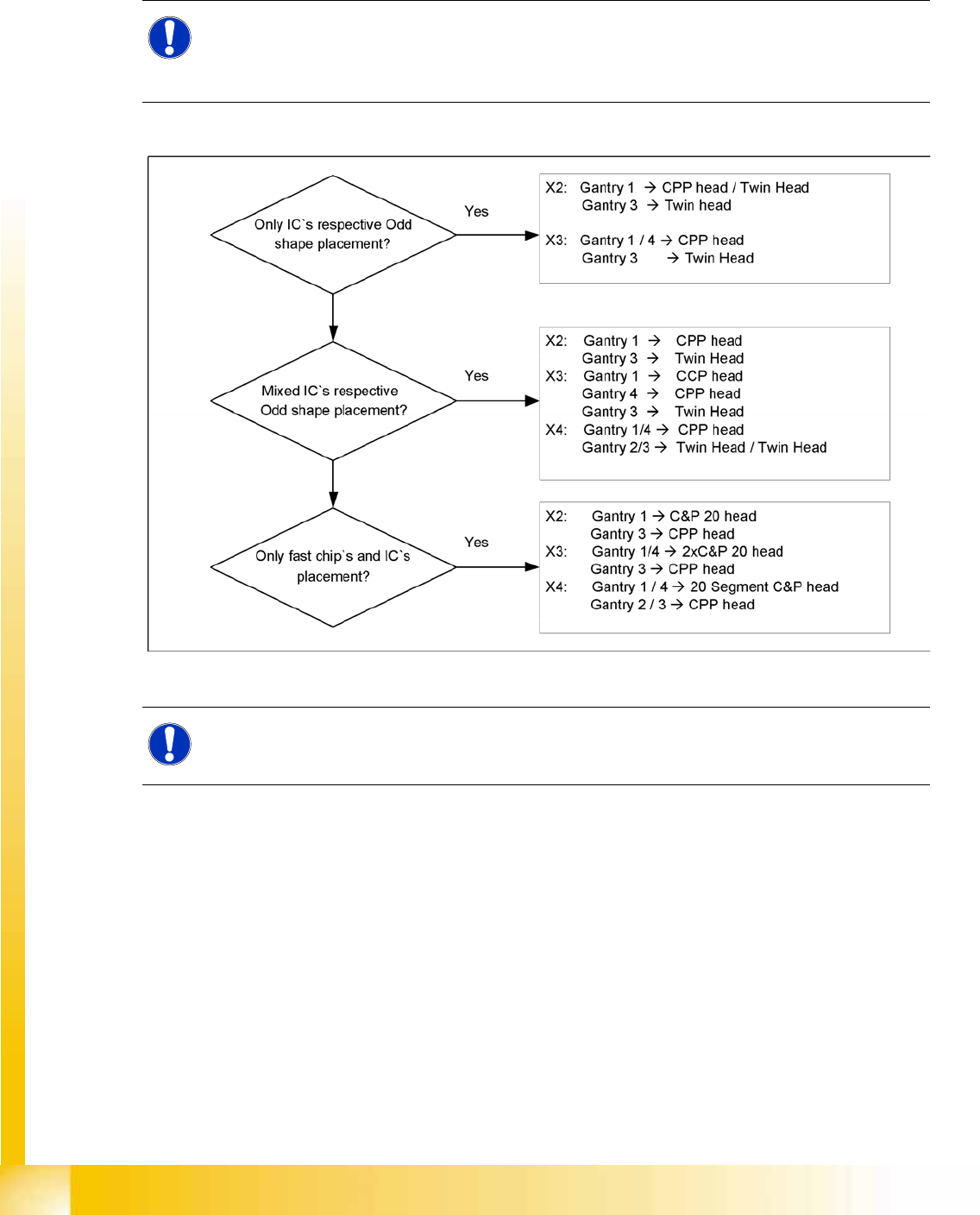
13.3 Head Modularity
13.3.1 Production requirements
Which decisions must be taken before head exchange?
13-2: Decisions before head exchange
NOTE: Reconfiguration of a SIPLACE X machine
The new configuration of the SIPLACE X machine should be maintained for a longer production
time for that product and should not be changed again on a weekly basis, as machine
reconfiguration and recalibration can take at least a day, depending on the machine type.
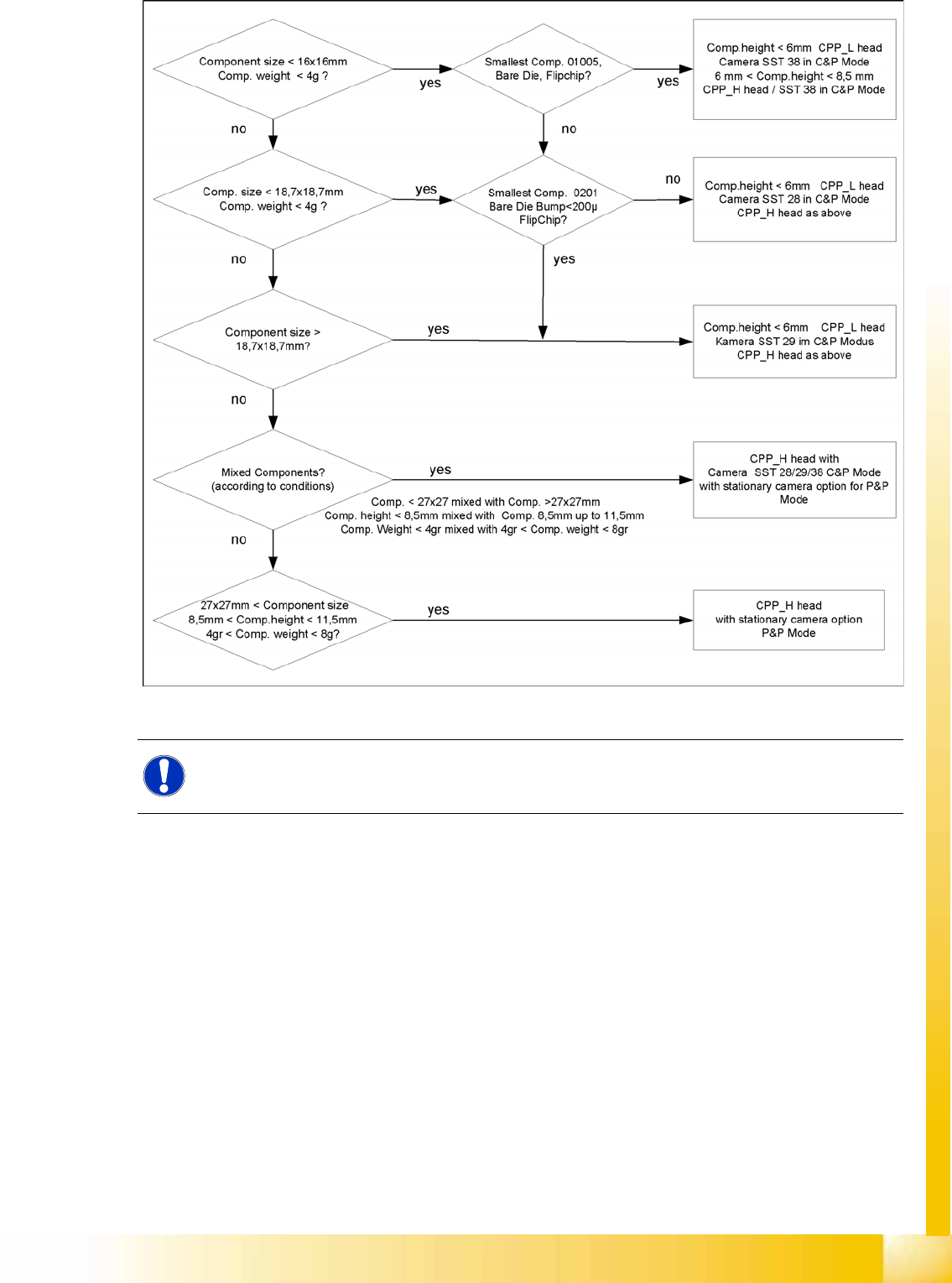
NOTE:
When using mixed placement, you need to decide which camera type is to be used for the CPP
head to achieve the widest possible component spectrum.
Head Modularity
Production requirements Head Modularity
Student Guide (FSE) SIPLACE X Series and X4I
Edition 01/2009 EN Head Modularity
521
13-3: Decision criteria for selection of position and camera types of CPP head
NOTE:
For the option Head Modularity, use the retrofitting guide "Head Reconfiguration Kits".