00196044-05 - sg x und x4i fse_en.pdf - 第572页
MTC2 MTC2 Calibration and Settings SITEST Calibration Flow Charts S tudent Guide (FSE) SI PL ACE X Series and X4I MTC2 Edition 01/2009 EN 576 14-38: Maximum position X Now calculate the center of the WT gap, so that the …
MTC2
SITEST Calibration Flow Charts MTC2 Calibration and Settings
Student Guide (FSE) SIPLACE X Series and X4I
Edition 01/2009 EN MTC2
575
14.3.2.2 Feed axis
Notes for calibration the zeropoint correction and transfer position into the machine.
1a. Calibration of zero point correction:
X Select
SITEST
-->
MTC
-->
Settings
X Select
Teach zero point.
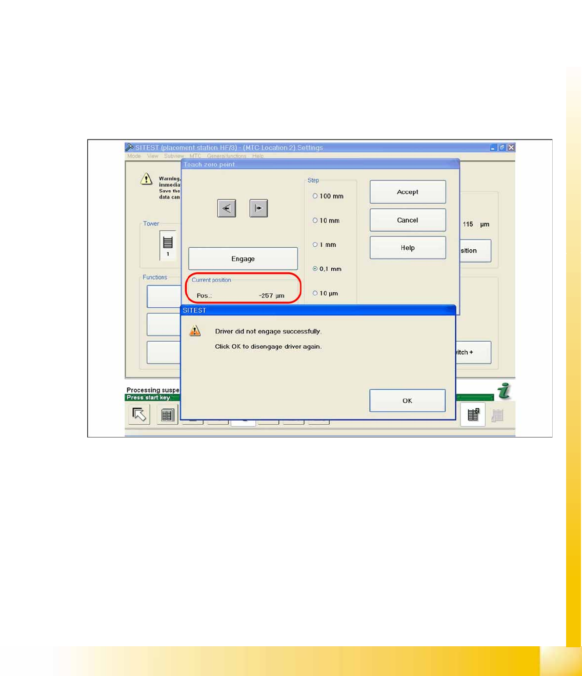
X Check the position of the driver with the
ENGAGE
.
In case the driver did not engaged successfully you must determine the middle of the notch of the waffel
pack tray.
The accurate adjustment is described below:
X If the feed axis is positioned so that the driver is unable to connect, move the feed axis into an
approximately correct position, in which the driver is able to engage. Now determine the minimum
and maximum position in which the driver can engage.
X Once the driver has engaged, gently tap the feed axis into the minimum position, until the driver is
just unable to engage (see diagram).
X Make a note of the position value shown.
14-37: Minimum position
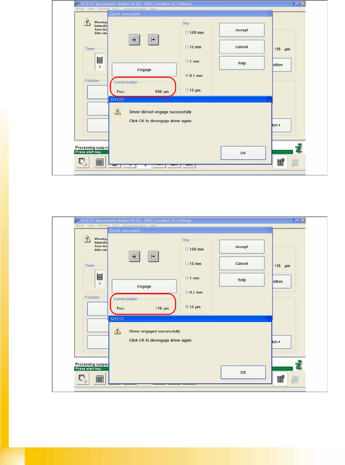
X Now gently tap the feed axis into the maximum position, until the driver is just unable to engage (see
diagram).
MTC2
MTC2 Calibration and Settings SITEST Calibration Flow Charts
Student Guide (FSE) SIPLACE X Series and X4I
MTC2 Edition 01/2009 EN
576
14-38: Maximum position
X Now calculate the center of the WT gap, so that the driver will always engage reliably.
e.g. |-257| + 596 = 853 divided by 2 = 426 µm
426 + the maximum position or minimum position or maximum position - 426 = approx. 169 µm
14-39: Correct position for the feed axis
X Check the driver position. The driver now should be correctly in the middle position of the notch of
the WTC.
X Click on
Accept
.
X Check the position of the driver for the other cassettes.
MTC2
SITEST Calibration Flow Charts MTC2 Calibration and Settings
Student Guide (FSE) SIPLACE X Series and X4I
Edition 01/2009 EN MTC2
577
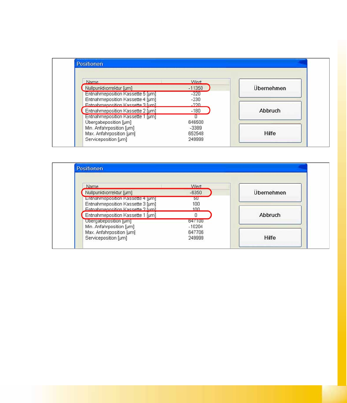
1b. Manuall Input of the Zero point correction
During calibration, the ZPC value is automatically entered in the
Removal position cassette 1
line of
the machine data.
Is this value to big, it is not possible to calibrate the max. and min. travel range of the feed axis.
Reason: The travel range will be calculated from the row
Zero point correction
. If this line shows the
value
zero
, the feed axis will move to the end position switch during measurement.
Solution: Enter the calibrated value for
Removal position cassette 1
in the
Zero point correction
line
of the machine data. In the
Position of removal Position cassette 1
line, enter the value
zero
.
SITEST:
X
MTC
-->
Axes
X Choose feed axis
X Select
Positions
14-40: Example: Input machine data tower 1
14-41: Example: Input machine data tower 2
X After the manuall Inputs, check the Zero point correction again.