00196044-05 - sg x und x4i fse_en.pdf - 第403页
Component Handling Overview Changeover Table S tudent Guide (FSE) SIPL ACE X Series and X4I Edition 01/2009 EN Component Handling 403 10 Component Handling 10.1 Changeover T able 10.1.1 Overview This chapter descr ibes t…

Twin Head
Room for Your Sketches and Notes Axis Control Twin Head D-Axis
Student Guide (FSE) SIPLACE X Series and X4I
Twin Head Edition 01/2009 EN
402
Component Handling
Overview Changeover Table
Student Guide (FSE) SIPLACE X Series and X4I
Edition 01/2009 EN Component Handling
403
10 Component Handling
10.1 Changeover Table
10.1.1 Overview
This chapter describes the preparation of components with the changeover tables, the corresponding
docking unit and the pneumatic cutter.
Up to four moveable changeover tables can be docked onto the X machine. The changeover tables are
automatically connected to and disconnected from the docking unit (mechanically and electrically) by
pressing a button. MTC2s can also be used with all X series machines (except X4I).
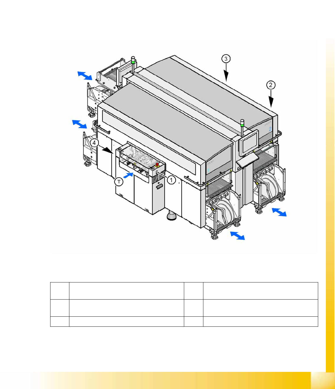
10-1: Shows the buttons for docking and undocking the COT‘s
Legend
1 Button for docking and undocking the
component trolley to location 1
3 Button for docking and undocking the
component trolley to location 3
2 Button for docking and undocking the
component trolley to location 2
4 Button for docking and undocking the
component trolley to location 4
T Direction of board transport
Component Handling
Changeover Table Overview
Student Guide (FSE) SIPLACE X Series and X4I
Component Handling Edition 01/2009 EN
404
10.1.1.1 Changeover Table (X Table)
The changeover table and the docking unit form a component supply unit.
Technical Data (X Table):
NOTE:
The SIPLACE X4I machine only supports C&P20A heads, X tables and the feeder types 8, 12
and 16 mm.
Feeder capacity 148 tracks width 8mm, 8mm X feeders
74 tracks width 12mm, 12mm X feeders
60 tracks width 16mm, 16mm X feeders tracks width mm.
Feeder locations: 4 changeover tables with integrated waste tape bins
40 locations, each with 8mm X feeders per component trolley at locations 1 and 3
34 locations, each with 8 mm X feeders per component trolley at locations 2 and 4
Feeder types Tape
Interface to the machine Automatic connection to machine during docking (no connection of cables needed)
Power supply
CAN bus connection
Closing the safety loop
Compressed air connection
Changeover table heights: Based on the conveyor height
830 mm ± 15 mm (standard)
900 mm ± 15 mm (SMEMA)
930 mm ± 15 mm (SMEMA)
950 mm ± 15 mm (SMEMA)