00196044-05 - sg x und x4i fse_en.pdf - 第122页
Communication and Control CAN Bus CAN I/O Module (SLIO) SIPLACE X S tudent Guide (FSE) SI PL ACE X Series and X4I Communication and Control Edition 01/2009 EN 122 4.3.10.1 DIP Switch on Main and Subdistributor (for V ers…
Communication and Control
CAN I/O Module (SLIO) SIPLACE X CAN Bus
Student Guide (FSE) SIPLACE X Series and X4I
Edition 01/2009 EN Communication and Control
121
4.3.10 CAN I/O Module (SLIO) SIPLACE X
SIPLACE X machines use 2 CAN I/O modules. Both modules are absolutely identical and are located in
sectors 2 (main distributor) and 4 (subdistributor). The introduction of the one wire bus system means
that there is now an additional board plugged into the I/O module (Interface 1-Wire CAT5).
Product characteristics:
Micro controller with integrated CAN controller
Data memory
Program memory (flash)
CAN interface with 9 pin connector and address alignment
16 digital Output 24 V with status LED
24 digital Input 24 V with status LED
Download interface
Power supply 24V
The 8 digital inputs can be logically linked with the help of a FPGA (freely programmable gate array).
The FPGA is used for incoming security messages.
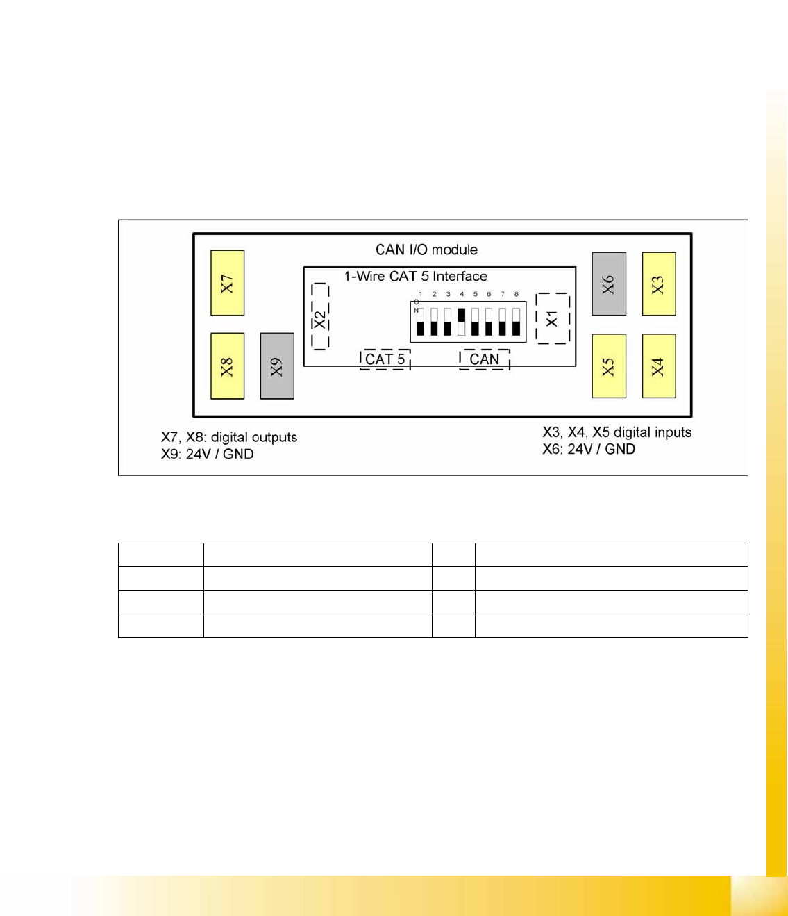
4-29: Example: Subdistributor
Legend
The jumper on the rear side activates the RS232 interface for service purposes.
X1 CAN Bus Interface to I/O module X2 RS232 interface
X3, X4, X5 Digital inputs 24V X6 24 V / GND
X7, X8 Digital outputs 24V X9 24 V / GND
CAT5 Interface 1-Wire connector CAT5 cable CAN CAN bus connector
Communication and Control
CAN Bus CAN I/O Module (SLIO) SIPLACE X
Student Guide (FSE) SIPLACE X Series and X4I
Communication and Control Edition 01/2009 EN
122
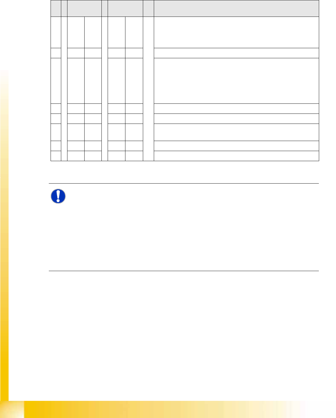
4.3.10.1 DIP Switch on Main and Subdistributor (for Version -03)
DIP switch on CAN I/O module (X-series from Ma No. B-326, X4I).
Applies for main distributors [03046225-xx] and subdistributors [03046226-xx].
Description of I/O Module
S Main
distributor
Subdistribut
or
Comments
1OFF OFF Gateway ON/OFF:
This switch opens the SUB CAN bus to address the tables and cutters
on the D1, D2 and D4 machines or the WPC on the X2 and X 3 from
SW 605.
2OFF OFF SW platform: ON: HF/HF3, OFF: D3, X series X4I
3OFF OFF Baudrate - ON = 1 MBit/s, OFF = 500 KBit/s:
This switch is only queried if switch S1 is set to ON.
D1, D2, X2, X3 with WPC (SW 605): ON
D4: OFF
X2, X3 without WPC, X4, X4I: The switch can be set to OFF here as
switch S1 is also set to OFF.
4OFF ON Location: ON: Subdistributor, OFF: Main distributor
5OFF OFF Not in use
6OFF OFF OFF: The connected Interface 1-Wire CAT5 board is active if the
switches on it are set to V2 and MA.
7OFF OFF HW reset for 1-Wire
8OFF OFF OFF: X series, X4I, D4, ON: D1/D2
NOTE: Description of I/O Module
The I/O assemblies of version 02 and 03 differ in that the "Interface 1-Wire CAT5" board is
integrated into version 03.
This means that this integrated "Interface 1-Wire CAT5" board can only be used for HF/HF3
machines.
X machines have the "Interface 1-Wire CAT5" connected as an additional module, due to the
CAT5 connection. By setting the switch on the interface to
MA
and
Version 02
the integrated
interface is switched off and the machine uses the additionally connected interface.
X The same I/O assembly is used for D series machines but with a different eSW. This results
in other DIP switch settings (see table above). The additionally connected interface is used
to address the components and cutters via a sub CAN bus.
Communication and Control
CAN I/O Module (SLIO) SIPLACE X CAN Bus
Student Guide (FSE) SIPLACE X Series and X4I
Edition 01/2009 EN Communication and Control
123
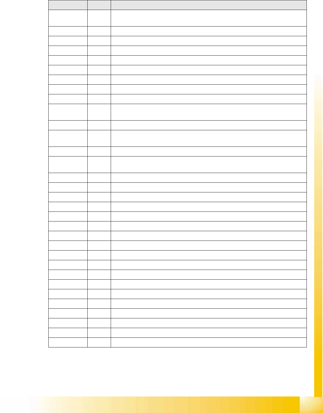
4.3.10.2 I/O Module, Main Distributor (Inputs) [new from B323: 03046225-01]
nc= not connected (Reserve)
Terminals I / O Description / Note
X3_1 Di0 M_NotAusSchleife1ok or M_Security Loop ("high" if all safety loops are closed
(protective hoods, emergency STOP buttons, component flaps, changeover tables).
X3_2 Di1 nc
X3_3 Di2 nc
X3_4 Di3 M_BeKlappe ("high" if one or more flaps open.)
X3_5 Di4 nc
X3_6 Di5 nc
X3_7 Di6 nc
X3_8 Di7 nc
X4_1 Di8 nc
X4_2 Di9 M_Bereit/Message changes from "low" to "high" if the SSK (K6) triggers, only
possible if "Steuerung_EIN" is on (control on).
X4_3 Di10 M_Vakuum OK
X4_4 Di11 M_PortalCrash1 "low" signal that gantries 1 and 4 are too close,"high" signal is
normal status
X4_5 Di12 nc
X4_6 Di13 M_ServoEnable1 or Control ON/ "high" signal - intermediate circuit voltage for X/Y
servo on axis unit 1 switched through. (K4 message)
X4_7 Di14 nc
X4_8 Di15 M_Drucksensor RV/Twin head "high" signal if compressed air level reached.
X5_1 Di16 24 V M_NotAus-Schleife 2 OK
X5_2 Di17 M_Haube2 "high" signal if cover 2 is closed
X5_3 Di18 M_BE-Tisch2 "high" signal if changeover table 2 is docked
X5_4 Di19 M_HaubeLP-Ausgabe "high"signal if the cover above the PCB output is closed.
X5_5 Di20 M_NotAusTasteLP-Ausgabe "high" signal if the emergency STOP button is unlocked.
X5_6 Di21 M_Haube3 "high" signal if cover 3 is closed.
X5_7 Di22 M_BE-Tisch3 "high" signal if changeover table 3 is docked
X5_8 Di23 nc
X6_1 nc
X6_2 nc
X6_3 GND
X6_4 nc
X6_5 nc
X6_6 nc
X6_7 nc
X6_8 nc