00196044-05 - sg x und x4i fse_en.pdf - 第574页
MTC2 MTC2 Calibration and Settings SITEST Calibration Flow Charts S tudent Guide (FSE) SI PL ACE X Series and X4I MTC2 Edition 01/2009 EN 578 2a. T ransfer position of the T ower 1 XL WTC X Select Teach transfer position…
MTC2
SITEST Calibration Flow Charts MTC2 Calibration and Settings
Student Guide (FSE) SIPLACE X Series and X4I
Edition 01/2009 EN MTC2
577
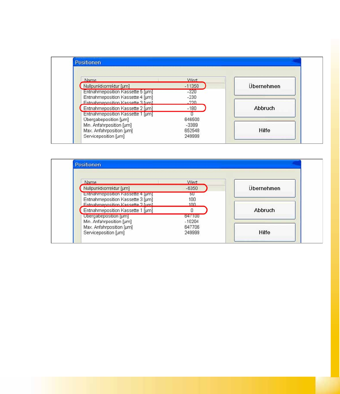
1b. Manuall Input of the Zero point correction
During calibration, the ZPC value is automatically entered in the
Removal position cassette 1
line of
the machine data.
Is this value to big, it is not possible to calibrate the max. and min. travel range of the feed axis.
Reason: The travel range will be calculated from the row
Zero point correction
. If this line shows the
value
zero
, the feed axis will move to the end position switch during measurement.
Solution: Enter the calibrated value for
Removal position cassette 1
in the
Zero point correction
line
of the machine data. In the
Position of removal Position cassette 1
line, enter the value
zero
.
SITEST:
X
MTC
-->
Axes
X Choose feed axis
X Select
Positions
14-40: Example: Input machine data tower 1
14-41: Example: Input machine data tower 2
X After the manuall Inputs, check the Zero point correction again.
MTC2
MTC2 Calibration and Settings SITEST Calibration Flow Charts
Student Guide (FSE) SIPLACE X Series and X4I
MTC2 Edition 01/2009 EN
578
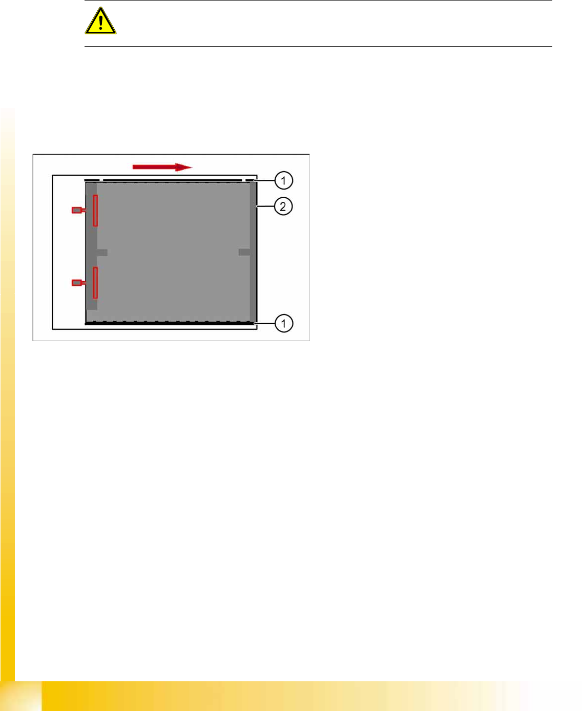
2a. Transfer position of the Tower 1 XL WTC
X Select
Teach transfer position
.
When you press the button to calibrate the Transfer position the tray moves approx. 5mm outside of the
feed axis.
X Open the cover and move the tray back in the direction to the lifting axes
X Then move the tray back in the direction to the machine and stop so that the plastic edge comes into
line with outer edge of the frame from the feed axis. You must do this in one step.
If the tray has been moved out with the feed axis, push it back in again and try to align it with the feed
axis frame in one step. This eliminates the tolerance between the driver and the tray gap and means
that you do not need to enter a pickup offset in the programming system.
ATTENTION:
If you have confirmed the calibration with
OK
in this situation, you will have calculated an
incorrect transfer position, which will lead to an incorrect pickup position for the Twin head.
14-42: Transfer position XL tray
Legend
1. Plastic edge of the WTC XL
2. Edge of the frame from the MTC
MTC2
SITEST Calibration Flow Charts MTC2 Calibration and Settings
Student Guide (FSE) SIPLACE X Series and X4I
Edition 01/2009 EN MTC2
579
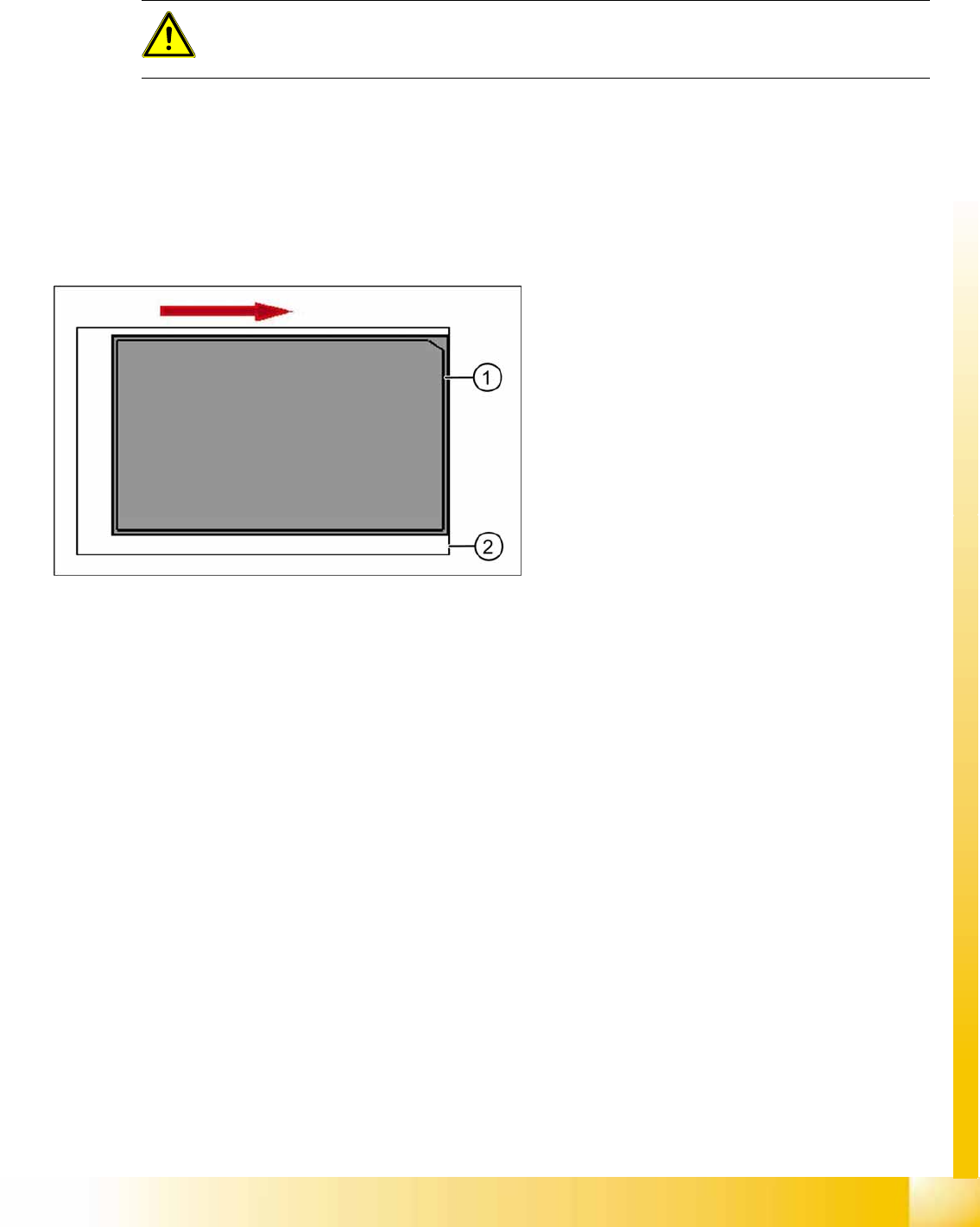
2b. Transfer position of the Tower 2 WTC
Select
Teach transfer position
, the tray will move out and come to a stop approx. 5 mm before the feed
axis ends.
X Open the cover.
X Move the tray in the direction of the machine and stop so that the plastic edge of the tray comes into
line with the frame of the feed axis.
X You must do this in one step.
If the tray has been moved out with the feed axis, push it back in again and try to align it with the feed
axis frame in one step. This eliminates the tolerance between the driver and the tray gap and means
that you do not need to enter a pickup offset in the programming system.
During the production the trays move a different way to her pick up position but the Y Position of the
machinen (pick up postion) of both trays is the same.
ATTENTION:
If you have confirmed the calibration with
OK
in this situation, you will have calculated an
incorrect transfer position, which will lead to an incorrect pickup position for the Twin head.
14-43: Transfer position JEDEC tray
Legend
1. Plastic edge of the WTC
2. Edge of the frame from the MTC