00196044-05 - sg x und x4i fse_en.pdf - 第489页
Calibration General Procedure Teaching Machine Positions S tudent Guide (FSE) SIPL ACE X Series and X4I Edition 01/2009 EN Calibration 493 12.5 T eaching Machine Positions 12.5.1 General Procedure The function Teaching m…

Calibration
General Explanation of Calibration Steps Head Mapping
Student Guide (FSE) SIPLACE X Series and X4I
Calibration Edition 01/2009 EN
492
12.4.9 Head Mapping
Head mapping is used to measure the linearity of the X and Y linear guides of the C&P head i.e. any
twisting of the gantry is compensated.
The C&P head places the calibration tool on the predefined target positions of the mapping plate. The
PCB camera measures the placement accuracy of these placements for the whole placement area. After
each measurement run, the calibration tool is remeasured with the component camera, before the next
target position on the mapping plate is approached.
The PCB camera measures the placement accuracy with the 4 fiducials on the calibration tool upper
side. This mapping determines a position-dependent offset to the existing head offset, in the placement
area.
12.4.10 Conveyor Sides
In modular conveyors, all conveyor sides can be adjusted. A stepping motor, driven by a positioning drive
toothed belt, is used to adjust the conveyor sides. The position of the rails are recognize with a BERO
and therefore we have different switch point on each conveyor rails. With this calibration the switch
points are optimized of the entire travel range of the width adjustment. The calibration is necessary that
all three Driver units move the conveyor rails parallel.
Automatic sequence (transport mapping):
The positioning drive is initialized and moves the conveyor side to the right-hand side (end position
switch).
The positioning drive recognizes the fixed conveyor side(s) (two for dual conveyor) and moves the
adjustable conveyor side(s) to the standard position of 55 mm.
The positioning drive moves the flexible conveyor side step by step (10mm steps) and determines
the offset of the positioning drive switching points in the various conveyor side positions.
This calibration is performed from left to right and back again.
The results are saved in the conveyor controller as correction values and taken into account later
when setting and measuring the conveyor width.
12.4.11 Conveyor Width Calibration
The conveyor width offset is determined with a board of any width. The width of the board is entered
manually and the current width of the conveyor is then determined. The difference is taken into account
internally as an offset.
NOTE:
Calibration needs to be performed for lanes 1 and 2.
Calibration
General Procedure Teaching Machine Positions
Student Guide (FSE) SIPLACE X Series and X4I
Edition 01/2009 EN Calibration
493
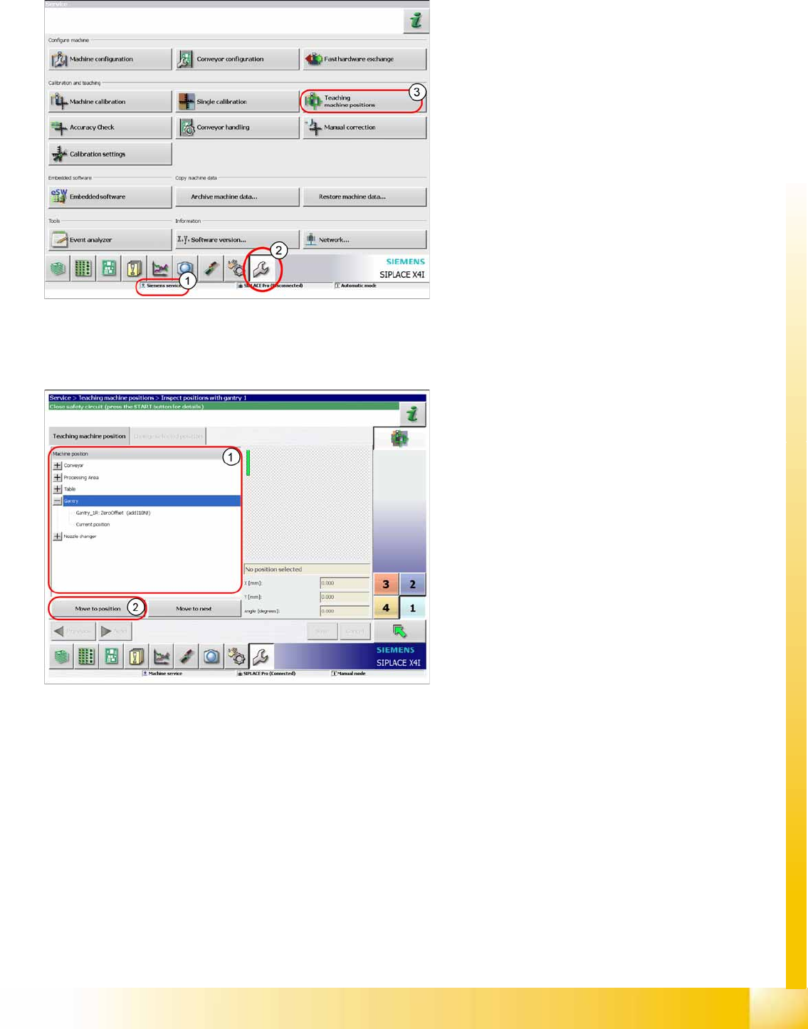
12.5 Teaching Machine Positions
12.5.1 General Procedure
The function Teaching machine positions can be
performed with the user level
Machine service
(1)
or
Siemens service
.
A successful overall machine reference run is a
precondition for this.
X Switch over to the service menu (2).
X Click on
Teaching Machine Positions
(3)
button, to start the wizard.
The machine positions are divided into the
following positions:
Conveyor
Processing area
Table
Gantry
Nozzle changer
X Select the position to be taught (1).
X Click on
Move to position
(2).
Calibration
Teaching Machine Positions General Procedure
Student Guide (FSE) SIPLACE X Series and X4I
Calibration Edition 01/2009 EN
494
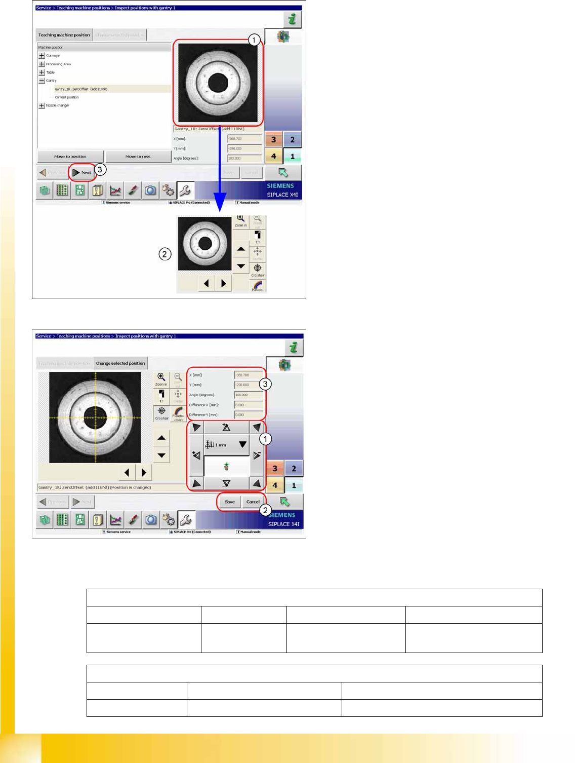
Explanation of terms and definitions
The machine positions will be approached.
X By clicking on the fiducial window (1) you will
see a range of other functions (2), such as
those for moving or centering the fiducial
window.
X Click on
Next
(3) to teach the fiducial
(position).
X Select the step size and teach the gantry, so
that the PCB camera is centered above the
fiducial (1).
X Click on the Save (2) button.
The field (3) shows the target values from the
machine data and the taught offset.
Zero Offset Fid_1L
Zero Offset Fid 1 L
Machine zero point Fiducial Placement area 1 L = left gantry (gantry 4)
R = right gantry (gantry 1)
CalibrationPart_5_Location_L
CalibrationPart 5 Location_L
Calibration pocket Small calibration tool for C&P20A Location on the left side, gantry 3 or 4