00196044-05 - sg x und x4i fse_en.pdf - 第193页
Energy and Compressed Air Supply Various Signals Power supply S tudent Guide (FSE) SIPL ACE X Series and X4I Edition 01/2009 EN Energy and Compressed Air Supply 193 5.2.10 V arious Signals 5.2.10.1 Sof tware Release (Sof…

Energy and Compressed Air Supply
Power supply Protective Contactor Combination K6 (SSK)
Student Guide (FSE) SIPLACE X Series and X4I
Energy and Compressed Air Supply Edition 01/2009 EN
192
5.2.9.2 How is SSK K6 Energized?
If the covers and the emergency STOP circuit are closed and K5 is deactivated, 24 V will be supplied to
terminals X1, X3 and X4, as soon as the GND is present at contact 6 (X6) - a state triggered by the
message
Safety loop OK
- and the start button has been pressed. This voltage allows K1 to be
energized and when its contacts close, K2 and K3 will energize. As soon as these contacts energize, K1
is de-energized. However K2 and K3 remain energized as their contacts have a self latching facility.
5.2.9.3 Pressing the ON Button
Assuming the ON button is pressed: 24 V is activated and will split into 2 paths.
1. : 24V is activated at the CAN I/O module 1. The signal from this module activates the CAN bus to
notify the machine controller that the ON button has been pressed. This deactivates the message
Press Start Key
.
2. : 24V is present at the power supply main distributor X16_2 and, from here, this signal (start
button) is sent to K1.4 (closed when main switch ON), K2.4 (break contact, NC), K3.4 (break contact,
NC), K4.4 (break contact, NC), K5 (make contact, NO), ending at pin 6 of the SSK. The 24 V is
activated when the following conditions are met:
Condition: When the machine controller gets the signal (1st path)
START BUTTON pressed
, it will set
an output via the CAN I/O module and supply A1 of contactor K5 with 24V (C_Software_On)
So when K5 is energized, the signal from 2nd path will flow to X4 of the SSK.
5.2.9.4 How Does the Protective Contactor Combination (SSK) Latch?
Condition: When K5 is energized, the following will happen:
L+ will get 24 V and will light up the first LED
Since L+ and X1 are internally connected, this 24 V signal will be fed back from X1 to the CAN I/O
module as a
SSK READY
.
The X4 on SSK will have 24 V temporary (only when ON is pressed), but it is enough to energize K1'
internal of the SSK. When K1’ is energized, K2' and K3' will also be energized internally of SSK -
only if X3 and X5 of SSK has 24 V with them.
How does X3 and X5 of SSK get the 24V?
If all covers are closed, the changeover tables are docked and the STOP button is not pressed, there
will be 24V present at K5 pin 3 and 4 via the emergency STOP circuit and from there at X3 and X5
of the SSK.
24V voltage on the X14 and X34 of the SSK (protective contactor combination)
When K2' and K3' are latched inside the SSK, pin 34 of SSK will have 24 V. Main task of them is to
power the tape cutter and to energize K2. (switching through of U, V, W of X/Y axes)
When K2’ and K3’ are latched inside the SSK, pin 14 of SSK will have 24 V. Main task of it is to
energize K3 and K4 (with a slight delay).
Energy and Compressed Air Supply
Various Signals Power supply
Student Guide (FSE) SIPLACE X Series and X4I
Edition 01/2009 EN Energy and Compressed Air Supply
193
5.2.10 Various Signals
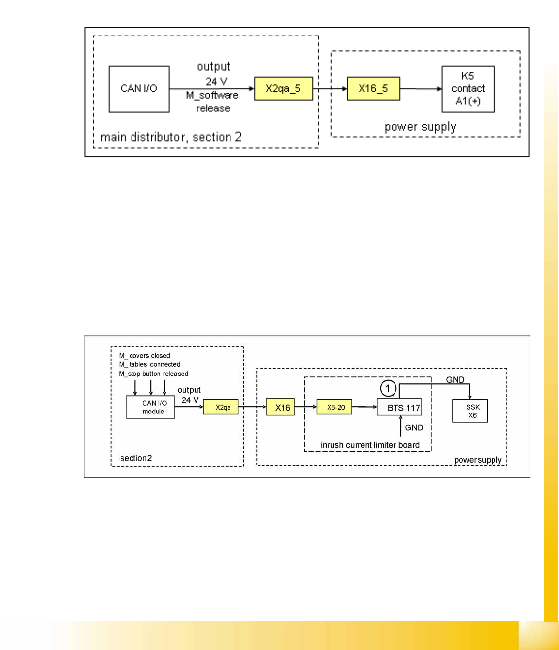
5.2.10.1 Software Release (Software Enabled)
The software release signal is given by the CAN I/O card when the machine controller software is fully
booted. This means that not only must the machine controller software be booted but communication
must be established to the Vision system, axis boards, CAN BUS, station computer and line computer
(unless it is operating in stand-alone mode). When the start button is pressed, the CAN I/O module
issues the 24V output signal and 24V is present K5, contact A1.
If the emergency STOP circuit is interrupted, the software release will not be issued.
5-19: Software release signal
5.2.10.2 OK Signal Safety Loop
The message
Safety loop OK
will be emitted by the CAN I/O module, if the following conditions have
been fulfilled:
All covers closed
All component tables connected
All emergency STOP buttons released
Emergency STOP circuit closed
The 24 V output from the CAN I/O module is present at the main voltage supply (inrush current limitation
board) and GND is switched through to contact 6.
5-20: Signal safety loop
Legend:
1. BTS 117: voltage switch for GND
This signal is transmitted to the power supply X8-20 and connects GND to SSK, contact X6.
Energy and Compressed Air Supply
Power supply Power Distribution
Student Guide (FSE) SIPLACE X Series and X4I
Energy and Compressed Air Supply Edition 01/2009 EN
194
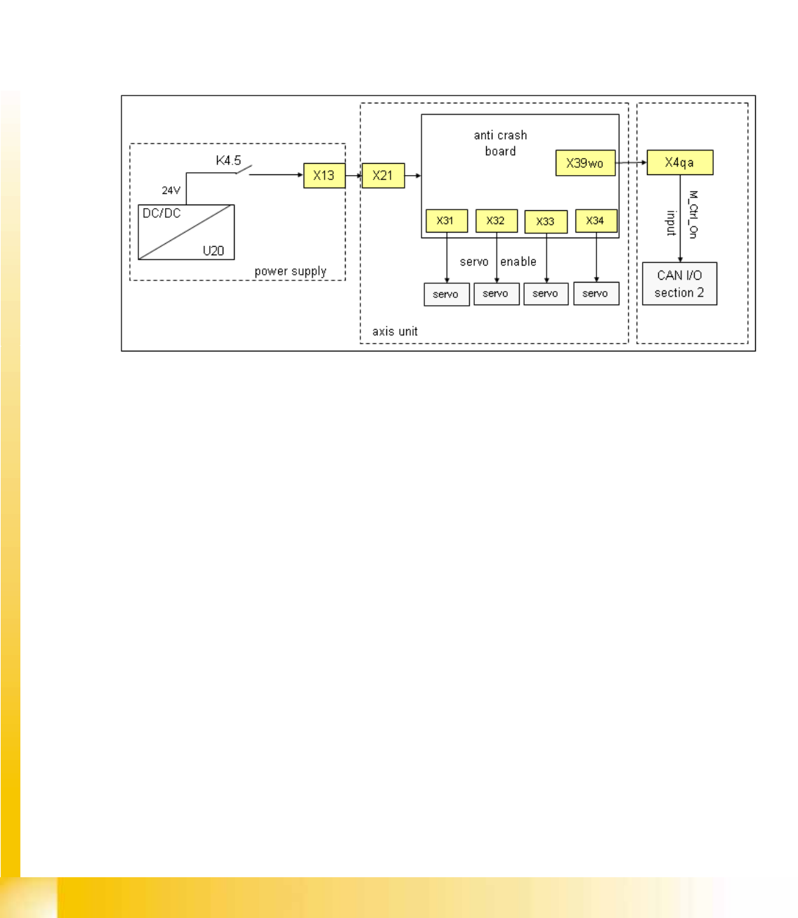
5.2.10.3 Control On Signal
If connector K4 of the power supply is enabled, the auxiliary contact K4.5 will close and 24 V (servo
release signal) will be present from the DC/DC converter to the distributor of the main power supply X13,
to the axis unit X21 and to the anti-crash board.
The introduction of the A364 also involved direct software realization of the anti-crash function on the
axis card.
Here it is split in 2 paths:
Path 1: 24 V present as
Servo enable signal
at the X/Y axis servo board, to enable the servo amplifier
(to switch GND to the servo board via optical coupler).
Path 2: 24 V present as
Ctrl_ON
signal at sector 2, connector X4qa and ends as M_Ctrl_On at the CAN
I/O module. The 4 main axis is allowed to move now into any position.
5-21: Control On signal
5.2.11 Power Distribution
The power distribution to the different sectors, gantries and heads is highly structured. 5V and 24 V,
generated by DC/DC converter U20 and U30 in main power supply, will first activate at distributor main
power supply, connector X16. Then at section 2, main distributor, connector X2qa and then at the
terminal block X1qa for general use, at connector X71qa and at last at connector X71ra, section 4.
52 V for camera illumination, generated by U7, is activated at main power supply distributor, X18, and
split into two paths.
Path 1: from X18, at section 2, X3qa, to terminal strip X1qa and then to the DC/DC converter Vision for
converting the 42 V needed for the IC/FC camera illumination. The voltage is also present via connector
X71qa to connector X71ra in sector 4 and to X1ra, ending at the DC/DC distributor Vision (42V are not
used here).
Path 2: (this path is currently not used) from X18 at sector 2, X3ra, to terminal strip X1ra and then to the
DC/DC distributor Vision for converting the 42 V needed for IC/FC camera illumination in this sector.
The voltage supply +/-15 V is generated at the power pack in the axis unit from the 52 V and is then
present at X4qa, at the terminal strip X1qa, for general distribution and use. The voltage is then present
via X74qa to X74ra in sector 4 to the intermediate distributor (not shown in the following diagram).