00196044-05 - sg x und x4i fse_en.pdf - 第77页
Overview C&P20A Head Overview of Components S tudent Guide (FSE) SIPL ACE X Series and X4I Edition 01/2009 EN Overview 77 3.2.9 C&P20A Head Technical Data Legend 1. Star with 20 segments (DP drives) 2. Board for …
Overview
Overview of Components SIPLACE Vision
Student Guide (FSE) SIPLACE X Series and X4I
Overview Edition 01/2009 EN
76
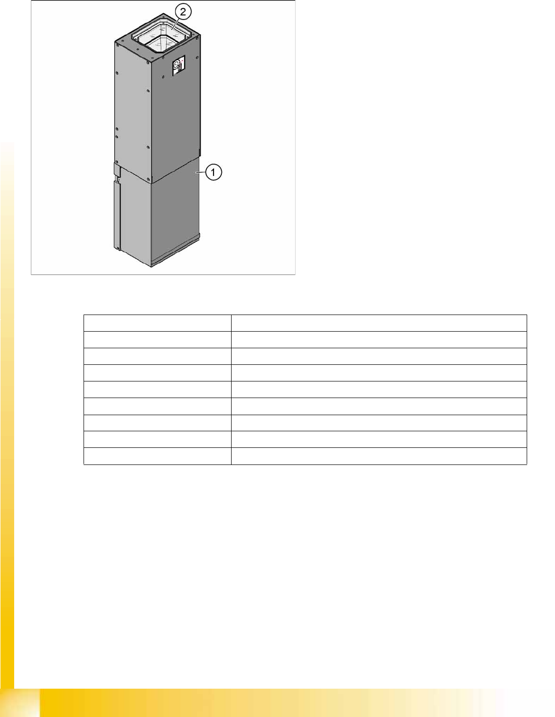
IC Camera SST33
Technical Data
Legend
1. Camera housing with integrated camera and
camera amplifier
2. Inside: the 6 illumination and lens levels
Component size 0.5 mm x 0.5 mm up to 55 mm x 45 mm for single measurement mode
Components 0402, MELF, SO, PLCC, QFP, electrolytic capacitors, BGA
Minimum lead pitch 0.3 mm
Min. ball pitch 0.45 mm
Min. ball diameter 0.25 mm
Field of vision 65 mm x 50 mm
Type of illumination Front-lighting (6 levels, programable as required)
Resolution 41µm/Pixel
Camera type.sst 33.sst
Overview
C&P20A Head Overview of Components
Student Guide (FSE) SIPLACE X Series and X4I
Edition 01/2009 EN Overview
77
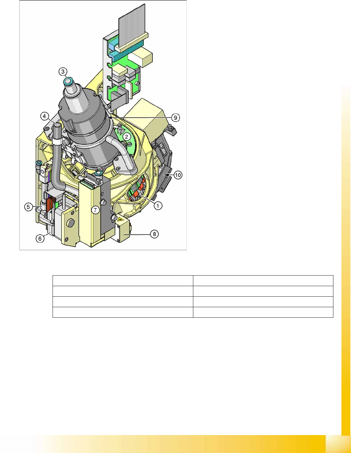
3.2.9 C&P20A Head
Technical Data
Legend
1. Star with 20 segments (DP drives)
2. Board for "hold circuit vacuum sensor"
3. Compressed air supply for holding, pickup and
place circuits
4. Cooling for X linear motor (discharged air from
pressure control valve)
5. Z axis return cylinder
6. Z linear motor with measuring system
7. Pressure control valve for pickup and place
circuit
8. Component sensor
9. Star motor with incremental encoder
10. Component Camera
Components 01005 to 2220, Melf, SOT, SOD
Max. component size 6 mm x 6 mm x 4 mm (L x W x H)
Min. component size 0.4 mm x 0.2 mm (01005)
Max. weight of component 1 g
Overview
Overview of Components C&P20A Head
Student Guide (FSE) SIPLACE X Series and X4I
Overview Edition 01/2009 EN
78
3.2.9.1 Description
The C&P20A head works according to the Collect&Place principle (C&P), meaning that twenty
components are picked from the feeder modules (X feeders only) in one cycle. The component sensor
checks the pickup/place positions, to see whether a component has been taken by the nozzle or placed
on a board. On the way to the placement position, the components are rotated into the correct placement
position and optically centered. Before placement is performed, the angle and X/Y position correction,
determined by the Vision system, is applied. The X/Y position correction is calculated into the placement
position, while the angle correction is applied separately to each segment. This is possible as each
segment can be rotated independently of the star position. The components are then carefully and
accurately placed down on the board, with an air blast.
The component camera is still integrated into the C&P20A head. This saves additional travel to the
external centering cameras.
Each segment has its own DP drive for rotating the components into the correct position. The segments
are therefore no longer rotated into the correct angle in one single star position but can now be rotated
separately from one another.
Each segment has its own vacuum generator.
The Z drive for the segments is realized via a linear motor with linear position measuring system, which
makes it highly accurate. In the pickup/place position, the Z axis moves the segments up or down
(vertical direction).
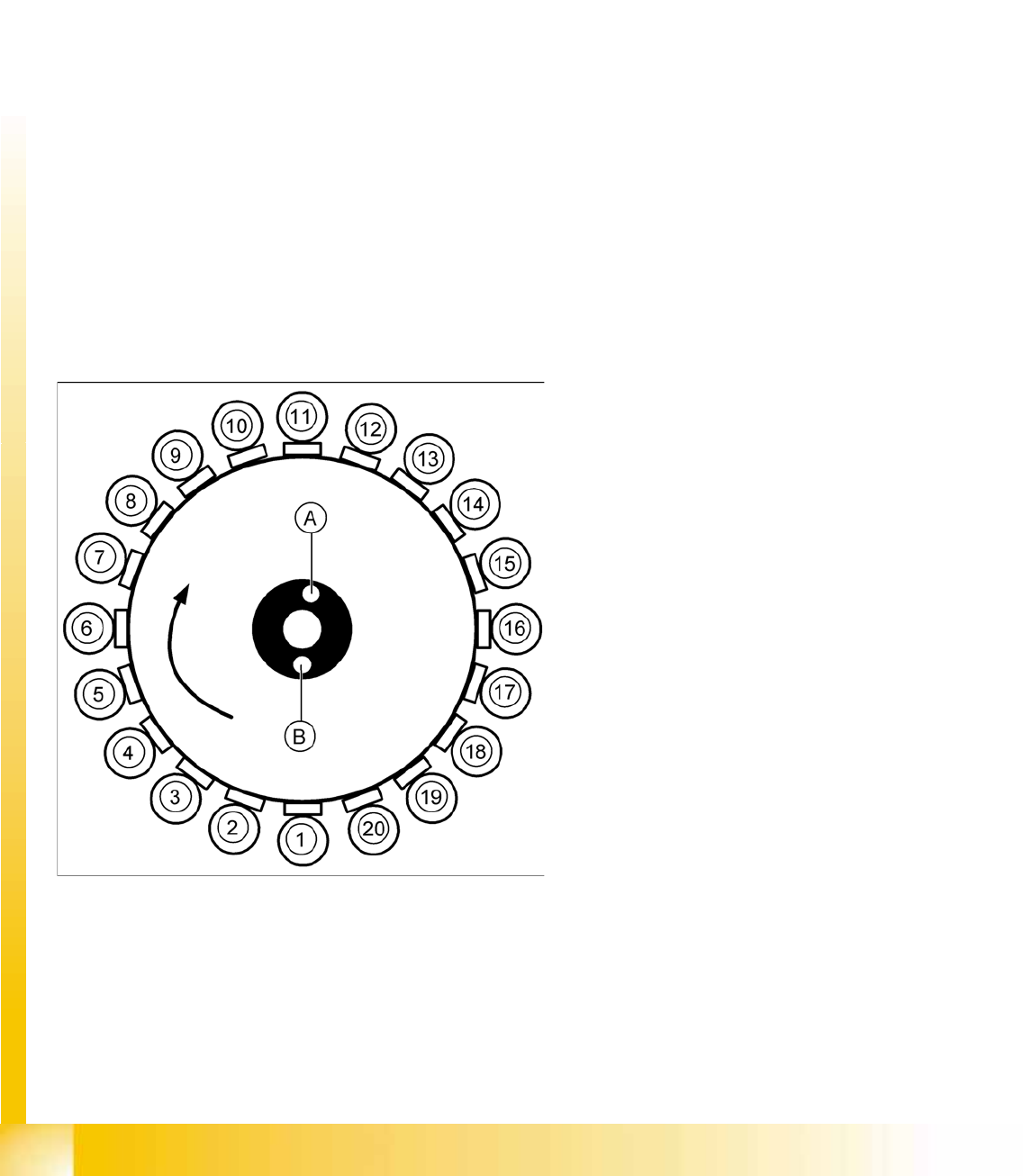
3.2.9.2 Overview of Functions for Star Stations 1 - 20
Star station 1:
Component pickup, placement or rejection
Component sensor: Checks whether component is present after pickup and before placement.
Component sensor: Checks whether no component is present after pickup and before placement.
Vacuum/air blast measurement for pickup/placement circuit
3-25: Overview of functions for star stations 1 - 20
Legend
1 to 20: star stations 1 to 20
A : Vacuum measurement holding circuit
B : Measurement of pickup/place circuit