00196044-05 - sg x und x4i fse_en.pdf - 第274页
C&P20A Pickup and Placement Cycle for C&P20A Standard Mode - Placement: Z Axis Up S tudent Guide (FSE) SI PL ACE X Series and X4I C&P20A Edition 01/2009 EN 274 7.4.26 St andard Mode - Placement: Z Axis Up 7.4…
C&P20A
Detailed Standard Pickup Procedure: Z Axis Up Pickup and Placement Cycle for C&P20A
Student Guide (FSE) SIPLACE X Series and X4I
Edition 01/2009 EN C&P20A
273
7.4.24 Detailed Standard Pickup Procedure: Z Axis Up
7.4.25 Standard Mode - Placement: Z Axis Down
Axis controller:
Enable signal for "light barrier down" function
LB down switches:
End signal Z axis positioning downwards;
Digital pressure control valve: switches "Air blast ON"
Pickup/placement position; air blast threshold "place component"reached? Yes.
7-38: Detailed pickup procedure: Z Axis Up
LB down switches:
Vacuum Threshold comp. picked reached?
YES
Z axis starts:
Z axis starts positioning upwards
Component sensor switches due to Z axis
movement:
Z axis position value; nozzle length +
comp.height measurement threshold
reached? YES
Z axis position in safety area:
reset light barrier state,
X, Y gantry axes start
start component feeder (communication to
feeder table)
Vacuum query:
Vacuum threshold for holding circuit reached?
YES
Star axis starts.
7-39: Detailed component placement procedure: Z Axis Down
In this mode (light barrier down) the placement
force at the C&P20A head is around 2N.
End position signal for X and Y axes--> Z axis
starts:
Positioning of Z axis downwards
Component sensor checks nozzle length with
component. Z axis measurement value -
nozzle length "with component" - threshold
reached? YES
End position signal for star axis:
Performs vacuum test "before placement".
"Vacuum closed" threshold reached? YES to
determine whether the component is held by
holding force on the nozzle.

C&P20A
Pickup and Placement Cycle for C&P20A Standard Mode - Placement: Z Axis Up
Student Guide (FSE) SIPLACE X Series and X4I
C&P20A Edition 01/2009 EN
274
7.4.26 Standard Mode - Placement: Z Axis Up
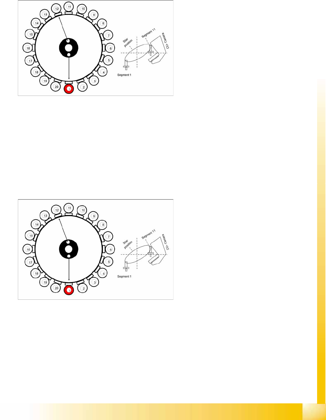
7.4.27 Optical Nozzle Query
After the reference run, the gantries move into the wait position and performs the first nozzle
scanning. During the production, a nozzle scanning run is performed after 350 head cycles (can be
set by Siemens service if required) and after the completion of the board currently processed. This
ensures that the nozzle quality is continually checked during the production process:
– All nozzles listed in the scan parameters of the station database will be measured by the
component camera.
– If there is any deviation from the defined size, shape or brightness, the machine will show the
message:
Nozzle worn down or contaminated
.
Tiny nozzles may touch the solder paste or the glue because of component shift and the minimum
component height.
The number of components per segment (number of head cycles), after the next nozzle query has
been performed, should be adjusted to the customer's process requirements. This check is always
performed after completing PCB processing.
7.4.28 Air Blast Control During Placement
The air blast is controlled by the digital pressure control valve, which can be programmed via the
component shape data in the SIPLACE PRO computer. In the component shape data, values between
0 and 255 bar can be set at "Advanced Handling". The standard value which is transmitted with the
component shape to the station is 150 mbar. This value needs to be reached to 80 % during placement.
7-40: Detailed component placement procedure: Z Axis Up
LB down switches:
...
Pickup/placement position; air blast threshold
"place component"reached? YES
Start signal for upwards movement
Z axis starts:
Z axis positioning upwards
Head firmware:
Digital pressure control valve: switches air
blast OFF
Reset "light barrier down" signal
Axis controller:
Z axis measurement value for nozzle "empty"
and
Z axis in safe area =
Enable X, Y gantry axes.
Vacuum query:
Vacuum threshold for holding circuit reached?
YES
Star axis starts.
C&P20A
Board Descriptions for C&P20A Settings
Student Guide (FSE) SIPLACE X Series and X4I
Edition 01/2009 EN C&P20A
275
7.5 Settings
7.5.1 Board Descriptions for C&P20A
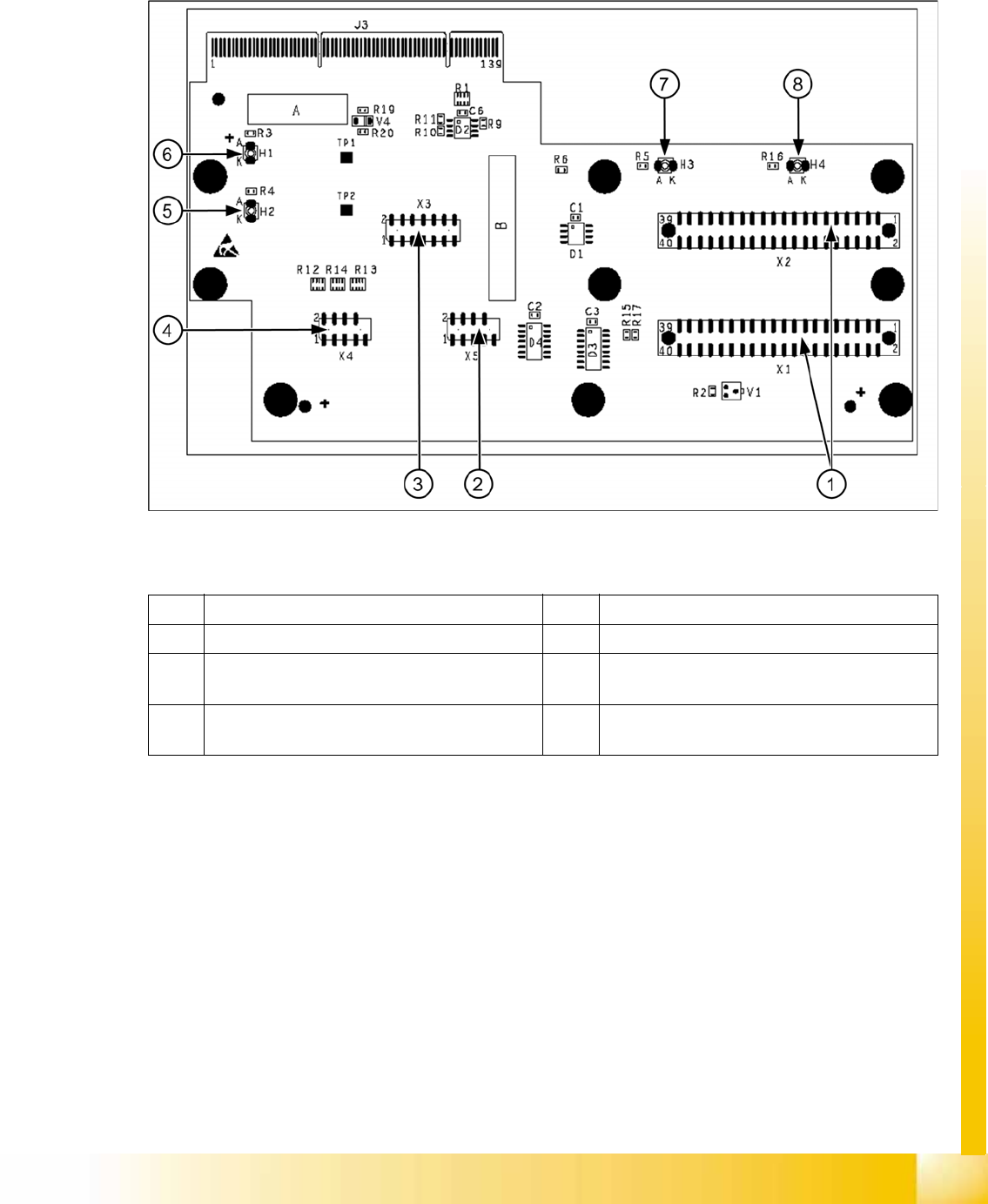
7.5.1.1 Head Adapter for C&P20A
7-41: Head Adapter for C&P20A
Legend
1 X1, X2 connection to intermediate distributor 5 H2 LED (green) for DP motor 24 V display
2 X5 Z axis track signals 6 H1 LED (red) for 24 V display at C&P20
3 X3 test connector: serial parallel interface (SPI)
bus
7 H3 LED (green) for component sensor display
4 X4 star track signals 8 H4 LED (red) for hardware error display at
C&P20A