00196044-05 - sg x und x4i fse_en.pdf - 第582页
MTC2 MTC2 Calibration and Settings Adjustments Lifting Axes S tudent Guide (FSE) SI PL ACE X Series and X4I MTC2 Edition 01/2009 EN 586 14.3.3.2 Guide Rails and St opper Bars T ools and accessories 1 set of Allen keys …
MTC2
Adjustments Lifting Axes MTC2 Calibration and Settings
Student Guide (FSE) SIPLACE X Series and X4I
Edition 01/2009 EN MTC2
585
Attach the connector.
X Switch the motor protection switch on.
X Attach the covers.
X Undock the MTC2 from the SIPLACE station (see User Manual).
X Crank up the MTC2 in a clockwise direction until it stops.
See also:
J
Tools and Equipment [
J
584]
Checking and setting the belt tension
X Carry out the relevant preparations (see Section ( Preparations
J
584 ) ).
X Measure the belt tension with the belt frequency measuring device in the following way:
Find the holes for the measurement head of the belt frequency measuring device on the lifting axis.
Two holes are provided for each of the dual toothed belts (see Section (14.3.3 Adjustments Lifting
Axes
J
583 ) ).
Attach the toothed belt tension stickers (Siemens item no. 00370691-0) onto the belts in this area.
Cause the belts to oscillate and measure their frequency.
You must set the belt tension if the measured frequency deviates from the nominal value [(200Hz ±
5Hz),(210Hz ± 5Hz) see note above]:
Turn the adjusting screws as far as they will go. Before doing this you will need to loosen the lock
nuts.
Loosen the four lock screws on the mounting plate of the motor.
Use the two adjusting screws to raise the belt tension (by turning in a clockwise direction) or lower it
(by turning in an anticlockwise direction), until the nominal frequency is achieved. Tighten the lock
nuts each time you measure the belt tension.
Firmly tighten the clamping screws and varnish them with red screw locking varnish.
Check the belt tension again.
Remove the belt tension stickers.
X Dock the MTC2 onto the SIPLACE station (see the User Manual).
X Check the zero offset of the lifting axis (see Section (14.3.2.1 Lifting axis
J
574 ) ), if you have
changed the belt tension.
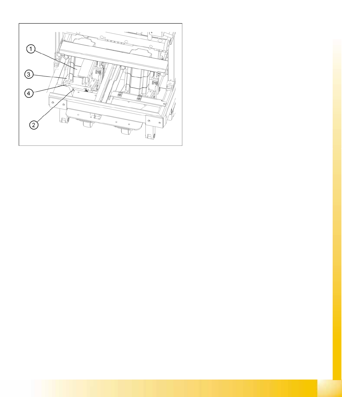
14-48: Setting the belt tension
Legend
1. Servo motor of the lifting axis (shown here for
tower 2)
2. Dual toothed belt (shown here for tower 2)
3. Mounting plate with clamping screws (shown
here for tower 2)
4. Adjusting screws with lock nuts (shown here
for tower 2)
MTC2
MTC2 Calibration and Settings Adjustments Lifting Axes
Student Guide (FSE) SIPLACE X Series and X4I
MTC2 Edition 01/2009 EN
586
14.3.3.2 Guide Rails and Stopper Bars
Tools and accessories
1 set of Allen keys
Preparations
X Move the lifting axis into the refill position for cassette 1 and completely set up the MTC2 with empty
cassettes (see User Manual).
X Set up every cassette with an empty WTC in the bottom and in the top level.
Checking and setting the guide rails, top
X Manually open the WTC interlock for each WTC which has been set up and check that the WTC can
be pulled out approx. 0.5 to 1mm up to the closed guide rail. When closing the WTC interlock, the
WTC must automatically click into place.
X Open the guide rail. When closing the guide rail, use a WTC which has been pulled out to check
either:
that the WTC engages in the WTC interlock again on its own or
that the guide rail cannot be closed.
X Set the position of the guide rail (by moving it in its fixing holes), if the behavior described above is
not observed.
Checking and setting the stopper bars, top
X Manually open the side interlock (leaf springs) for each WTC and check that the WTC can be pushed
through approx. 0.5 to 1mm up to the stopper bar. When closing the interlock, the WTC must click
into place automatically.
X Set the position of the stopper bar (by moving it in its fixing holes), if the behavior described above
is not observed. If necessary, remove the covers behind the doors.
Check on tower 1 that a WTC XL with 25 mm-high components can be transported without colliding
with the stopper bar. If necessary, correct the position of the stopper bar.
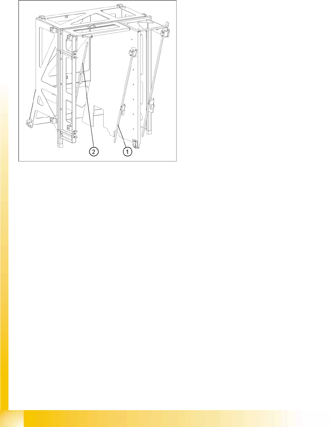
14-49: Guide rails and stopper bars in the upper frame
Legend
1. Guide rail (shown here for tower 1)
2. Stopper bar (shown here for tower 1)
MTC2
Adjustments Lifting Axes MTC2 Calibration and Settings
Student Guide (FSE) SIPLACE X Series and X4I
Edition 01/2009 EN MTC2
587
Checking and setting the stopper bars, bottom
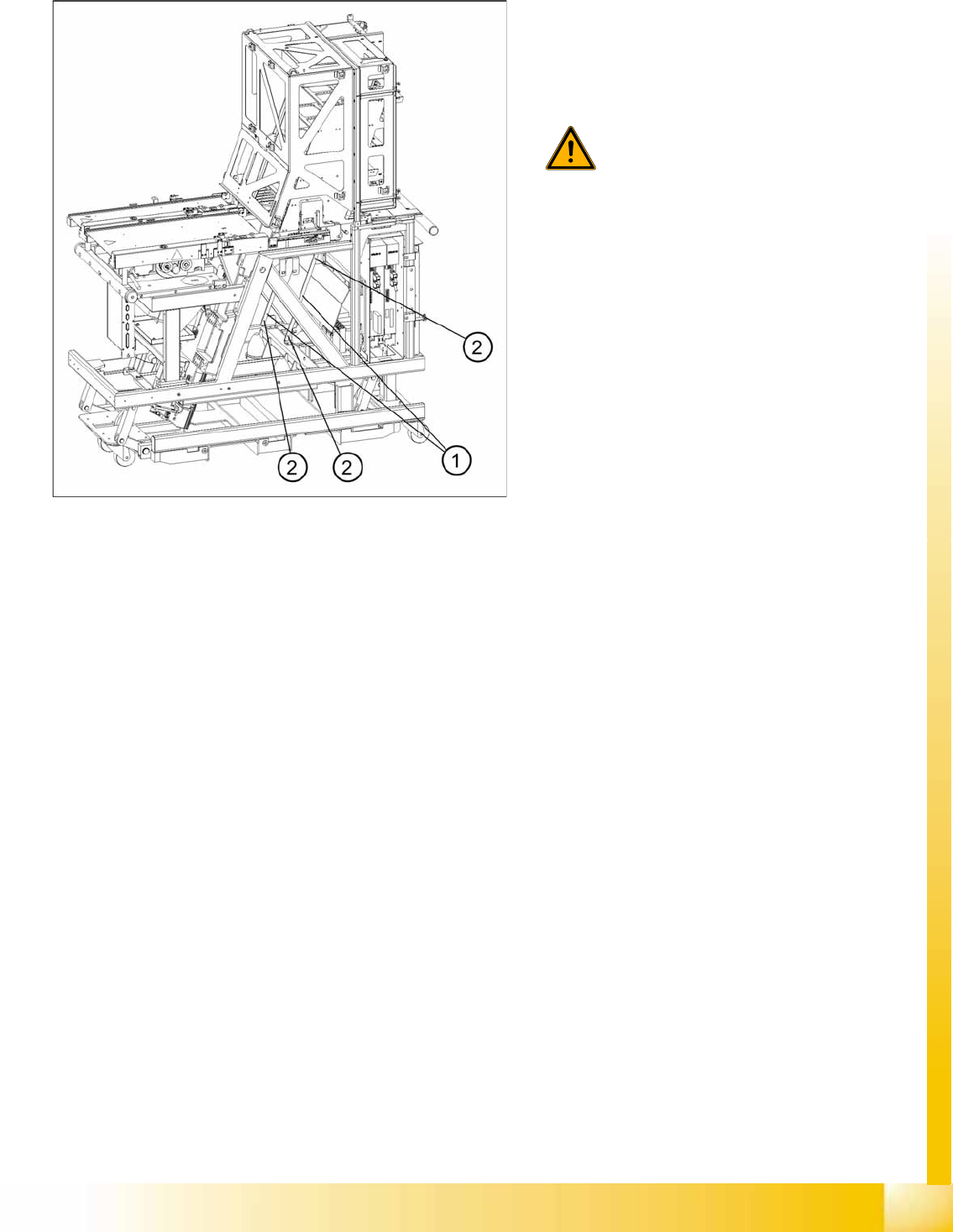
14-50: Guide rails, bottom
X Move the doors fully down
X Remove the side covers
X Set the position of the guide rails until they are
approx. 0.5 through 1mm away from the
WTCs.
WARNING:
The stopper bar and guide rail must
under no circumstances touch the
WTCs!
Legend
1. Guide rails
2. Fastening screws