00196044-05 - sg x und x4i fse_en.pdf - 第154页
Communication and Control One Wire Bus One Wire Bus SIPLACE X Machine S tudent Guide (FSE) SI PL ACE X Series and X4I Communication and Control Edition 01/2009 EN 154 4.5.3 One Wire Bus SIPLACE X Machine The structure of…

Communication and Control
Function Control and Troubleshooting for Service Work One Wire Bus
Student Guide (FSE) SIPLACE X Series and X4I
Edition 01/2009 EN Communication and Control
153
CAN Bus Commands for the Status Query Reject Bin Nozzles
Command:
6a 32 04
6a 32
--> command for status request component reject bin
04
--> Gantry 4
Select
Send
Acknowledge:
6a 00 00
--> reject bin not present
6a 00 01
--> reject bin present
CAN Bus Commands For Checking the Temperature Sensors
Command:
6e 11 01 01 28 10
6e 11
--> command
01
--> not def.
01
--> Gantry 1
28
--> Subsystem temperature
10
--> Temperature sensor at top, on the head plate (16)
Select
Send
Acknowledge:
6e 00 1c 4b
-->
6e 00
--> command
1c
--> Temperature value 1c hex --> 28°C
Command:
6e 11 01 01 28 11
6e 11
--> command
01
--> not def.
01
--> Gantry 1
28
--> Subsystem temperature
11
--> Temperature sensor at bottom, on the head plate (17)
Select
Send
Acknowledge:
6e 00 1d 4b
-->
6e 00
--> command
1d
--> Temperature value 1d hex --> 29°C
CAN Bus Commands for Initializing the One Wire Bus
Command:
3d 01
3d 01
--> initialization command
Select
Send
Acknowledge:
3d 00 01
Initialization successful.
NOTE:
The reject bins request is sent via the message loop. This means that you must first close the
whole security loop (table, cover,...) before the software can check and display the state of the
message loop (e.g.missing reject bins).
Communication and Control
One Wire Bus One Wire Bus SIPLACE X Machine
Student Guide (FSE) SIPLACE X Series and X4I
Communication and Control Edition 01/2009 EN
154
4.5.3 One Wire Bus SIPLACE X Machine
The structure of the SIPLACE X and X4I machines has been changed. This results in a different
hardware structure of the bus system and the subsystems to the hardware components.
During the initialization procedure, the subsystems independently log themselves on to the one wire bus
via the public byte. The public byte is sent via the CAN ID +3hex of the relevant subsystem. If the state
of a subsystem changes, the subsystem reports automatically and without a request from the
application.
See also:
J
Allocation of Subsystems to the Hardware Components [
J
147]
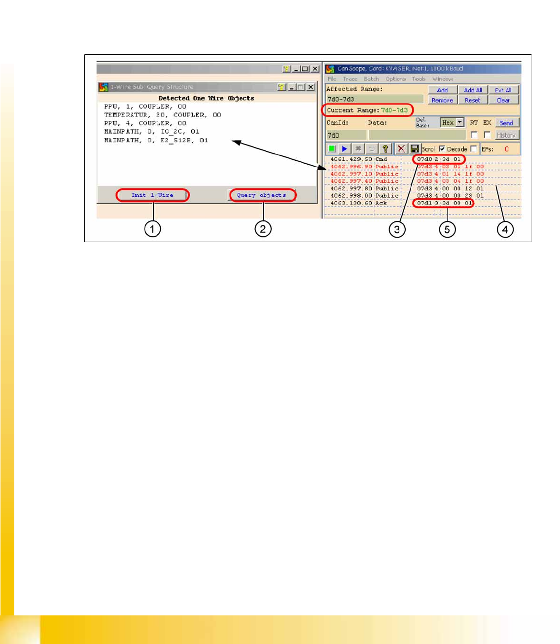
4.5.3.1 One Wire Communication
4-54: Communication with the one wire interface RS232 on the I/O module
Legend
1.
Init 1 Wire
sends the command via the CAN ID
7d0
(PA1)
2.
Query objects
shows the decoded public bytes.
3. Net window:
07d0 3d 01
Command initialization for the one wire bus.
4. 5 public bytes from subsystem 1-Wire CAT5 interface on the I/O module
1.
03 01 1f 00
-->
03
Subsystem NC /
01
Gantry /
1f
Coupler
2.
01 14 1f 00
-->
01
Subsystem temperature gantry 1/4 /
14
1k EEPROM /
1f
Coupler
3.
03 04 1f 00
-->
03
Subsystem NC /
04
Gantry /
1f
Coupler
4.
00 00 12 01
-->
12
I/O component and EEPROM
5.
00 00 23 01
-->
23
4k EEPROM
5. Acknowledge (Ack) command CAN ID +1hex -->
3d 00 01
Communication and Control
One Wire Bus SIPLACE X Machine One Wire Bus
Student Guide (FSE) SIPLACE X Series and X4I
Edition 01/2009 EN Communication and Control
155
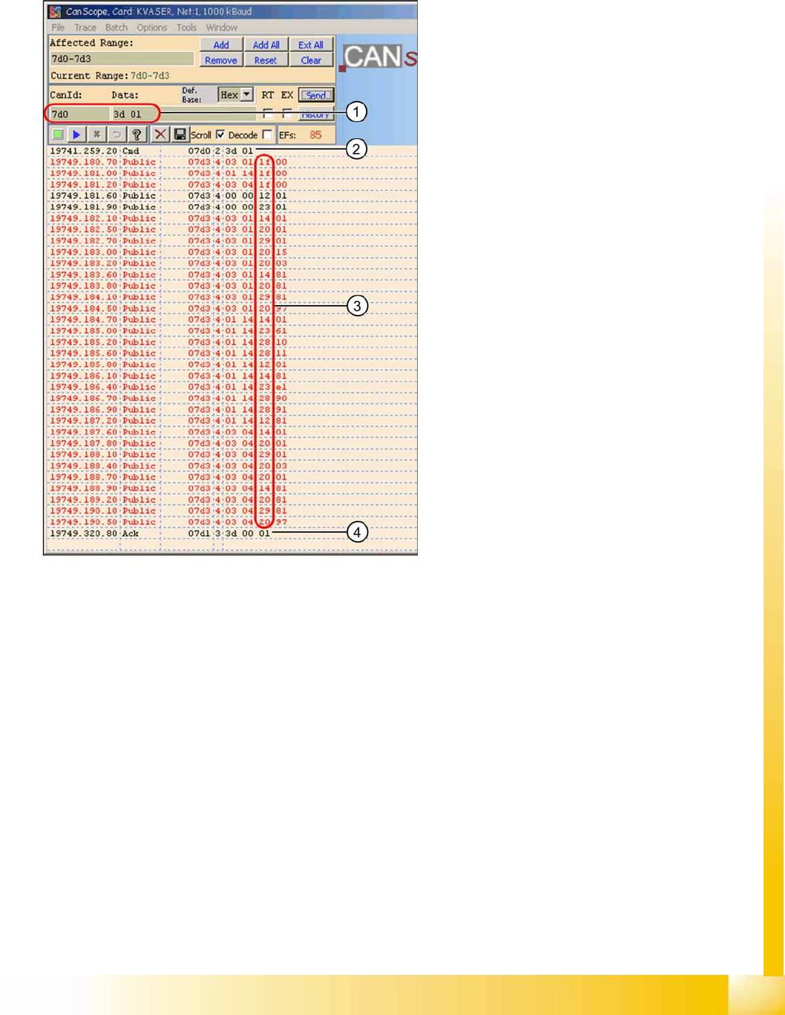
4.5.3.2 Overview of One Wire Bus Initialization
Legend
1. CAN BUS command for initialization
2. CAN BUS command sent.
3. Subsystems report, public bytes
1f
--> Coupler
12
--> IO component with EEPROM
14
--> 1k EEPROM
20
--> 4 channel A/D
23
--> 4k EEPROM
28
--> Temperature
29
--> 8-fold IO component
4. Ack initialization successful.