00196044-05 - sg x und x4i fse_en.pdf - 第595页
MTC2 Converting the power supply MTC2 Calib ration and Settings S tudent Guide (FSE) SIPL ACE X Series and X4I Edition 01/2009 EN MTC2 599 14.3.5.3 V olt age distributor terminal X01 14.3.5.4 Motor Circuit Breaker 14-61:…
MTC2
MTC2 Calibration and Settings Converting the power supply
Student Guide (FSE) SIPLACE X Series and X4I
MTC2 Edition 01/2009 EN
598
14.3.5 Converting the power supply
To operate the MTC2 in the USA or in Japan, the power supply needs to be changed from 400 V, 50 Hz
to 208/204 V, 50/60 Hz.
14.3.5.1 Tools and Equipment
1 set of screwdrivers
3 additional bridges
14.3.5.2 Procedure
NOTE:
To convert the power supply from 208/204 V to 400 V, the same procedure must be carried out
in the reverse order.
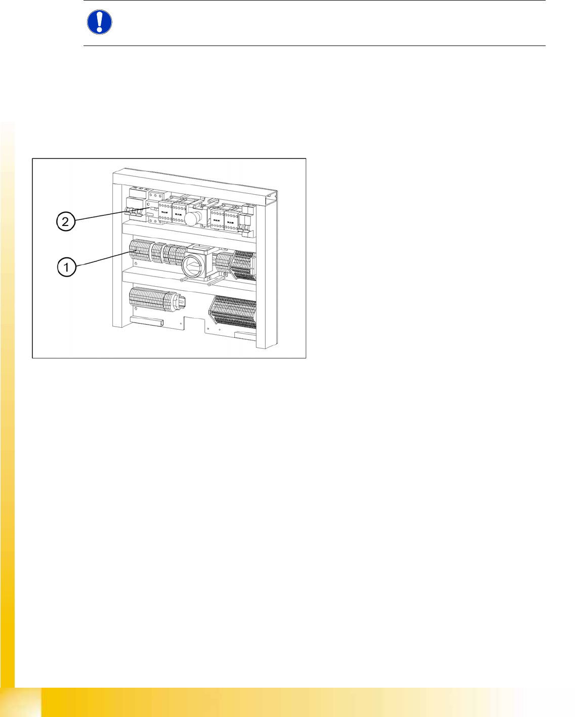
14-60: Electronics board
Legend
1. Bridges on the voltage distributor terminal X01
2. Motor Circuit Breaker
MTC2
Converting the power supply MTC2 Calibration and Settings
Student Guide (FSE) SIPLACE X Series and X4I
Edition 01/2009 EN MTC2
599
14.3.5.3 Voltage distributor terminal X01
14.3.5.4 Motor Circuit Breaker
14-61: Voltage distributor terminal X01
Legend
1. Bridges on the voltage distributor terminal X01
X Removing the three bridges between 2-3, 6-7
and 10-11.
X Connect the six bridges between 1-2, 3-4, 5-6,
7-8, 9-10 and 11-12.
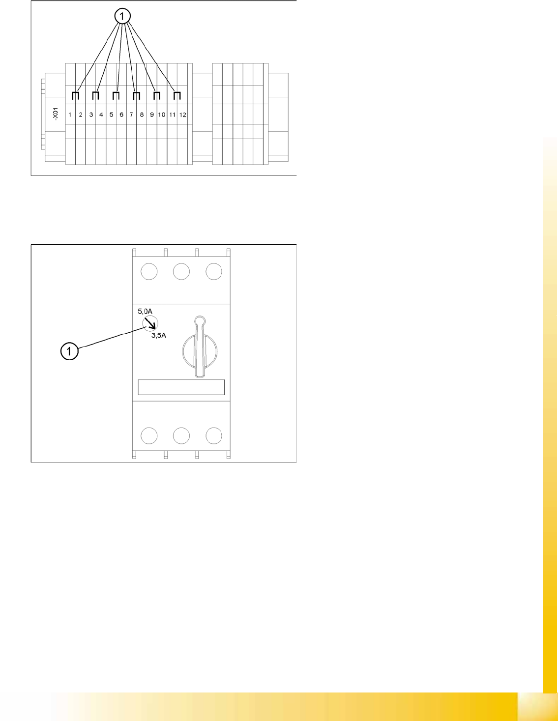
14-62: Motor Circuit Breaker
Legend
1. Rotary regulator of the motor protection switch
X It is always 3.5 A.

MTC2
MTC2 Calibration and Settings Machine Data
Student Guide (FSE) SIPLACE X Series and X4I
MTC2 Edition 01/2009 EN
600
14.3.6 Machine Data
14.3.6.1 General machine parameters
Software version: Date 11.2004
Serial number, MTC2: 214
Delta fiducial transfer position: 10000
14.3.6.2 Machine parameters for tower 1
Machine parameters for the lifting axis on tower 1
Positions
Offset, zero position: -500.300 mm
Position of operator removal position, cassette 1: 0 mm
Position of operator removal position, cassette 2: 103.150 mm
Position of operator removal position, cassette 3: 206.250 mm
Position of operator removal position, cassette 4: 309.450 mm
Position of operator removal position, cassette 5: 412.600 mm
Position of WTC removal position, cassette 1: 28.300 mm
Position of WTC removal position, cassette 2: 131.500 mm
Position of WTC removal position, cassette 3: 234.500 mm
Position of WTC removal position, cassette 4: 337.800 mm
Position of WTC removal position, cassette 5: 440.950 mm
Minimum position: -3.233 mm
Maximum position: 573.472 mm
Service position: 165.000 mm
Travel parameters
Default speed, WTC: 50
Default acceleration, WTC: 50
Acceleration, lower threshold value: 1
Acceleration, upper threshold value: 50
Acceleration, axis command: 50
Acceleration, axis command: 50
NOTE:
The machine parameters listed are only an example of a data record. The individual values can
be different for each MTC2 .
WARNING:
Incorrectly set machine data can result in a crash between the lifting and feed axes or at the limit
positions of these axes.