00196044-05 - sg x und x4i fse_en.pdf - 第329页
Collect, Pick and Place Head (CPP) Procedure for Picking Up Components Pickup and Placement Cycle for CPP S tudent Guide (FSE) SIPL ACE X Series and X4I Edition 01/2009 EN Collect, Pick and Place Head (CPP) 329 Legend 1.…
Collect, Pick and Place Head (CPP)
Pickup and Placement Cycle for CPP Turning Nozzles 1 to 12 to the Pickup Angle (0° or 90°)
Student Guide (FSE) SIPLACE X Series and X4I
Collect, Pick and Place Head (CPP) Edition 01/2009 EN
328
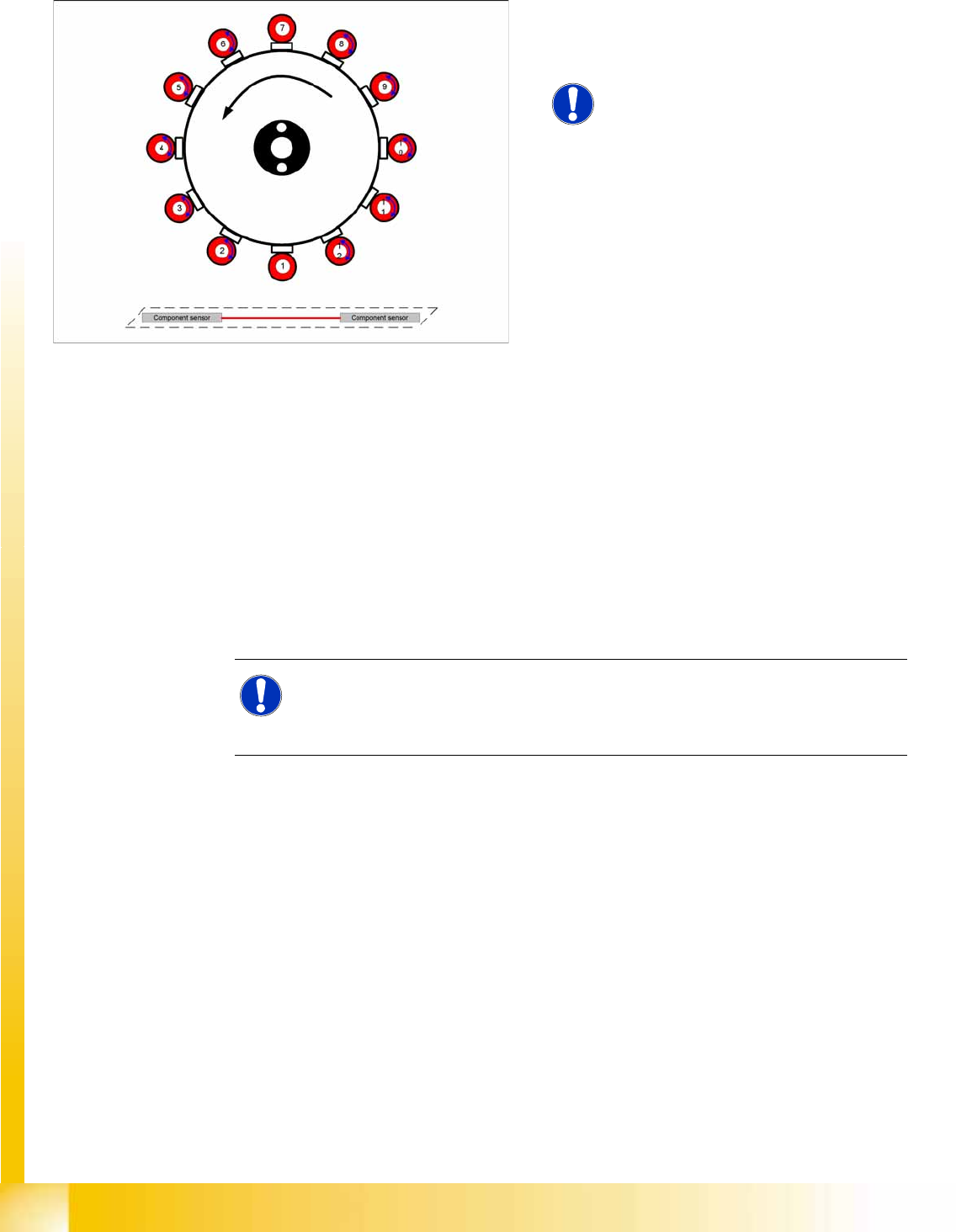
8.4.5 Turning Nozzles 1 to 12 to the Pickup Angle (0° or 90°)
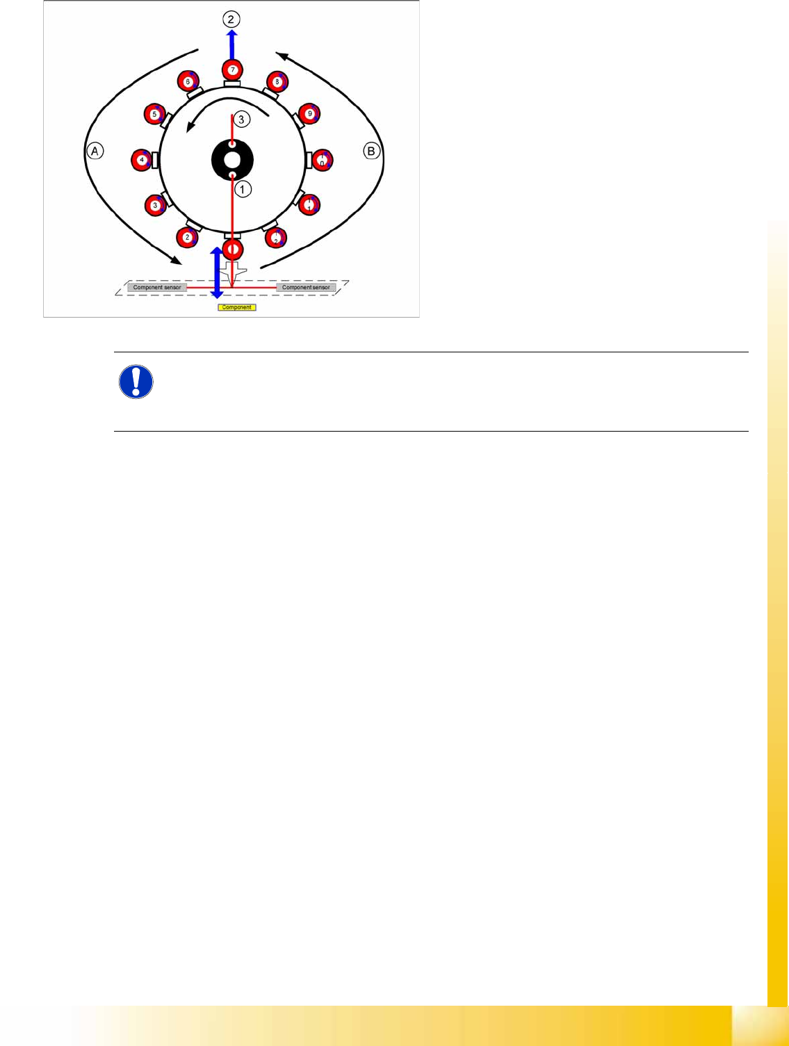
8.4.6 Procedure for Picking Up Components
Prerequisite: The nozzle must be in the correct pickup position (0° or 90°).
1. The gantry moves over the pickup position of the 1st component.
2. Valve 1 of the valve terminal is switched on.
3. Vacuum measurement in pickup/place circuit „open“
4. The Z axis travels down and interrupts the component sensor.
5. The Z position is read out, the nozzle length calculated and compared to the reference length from
the height reference run.
1. The vacuum is switched on (pressure control valve - either "early vacuum" or with light barrier down,
depending on the pickup profile.)
2. The Z axis moves up. A vacuum check is performed to determine whether there is a component on
the nozzle.
3. The component sensor is released and the Z position is read out. Either the component height is
calculated or a presence check is performed.
4. A vacuum check is performed when the Z axis is in the top position.
5. The star is rotated and more components are picked up.
6. The component on segment 1 is rotated into the placement position by the DP drive (area A).
7. A component is picked up at segment 7.
8. The component at segment 1 is optically centered under the component camera.
9. A placement angle correction run is performed after optical centering (area B).
10. Once all 12 components have been picked up, the pickup process has finished.
8-11: Turning segments 1 to 12 to the pickup angle (0° or 90°)
The segments in the CPP head are turned in
succession, from segment 1 to 12, to the
required pickup angle of 0° or 90°.
NOTE:
Each segment has its own DP drive
NOTE:
This calculated nozzle length is used when moving up in the placement cycle, to
check whether the component is placed. If a length difference of -0.15 mm or +0.1
mm is found, a warning will be issued: Replace nozzles.
Collect, Pick and Place Head (CPP)
Procedure for Picking Up Components Pickup and Placement Cycle for CPP
Student Guide (FSE) SIPLACE X Series and X4I
Edition 01/2009 EN Collect, Pick and Place Head (CPP)
329
Legend
1. Vacuum measurement pickup/place circuit
2. Optical centering SIPLACE Vision
3. Vacuum measurement hold circuit
A : Rotate component into placement angle
B : Placement angle correction after optical
centering
NOTE:
All vacuum measurements during the placement process are performed in the background and
do not produce any error messages. The error messages concerning missing components etc.
are produced only by the component sensor.
Collect, Pick and Place Head (CPP)
Pickup and Placement Cycle for CPP Procedure for Placing Components
Student Guide (FSE) SIPLACE X Series and X4I
Collect, Pick and Place Head (CPP) Edition 01/2009 EN
330
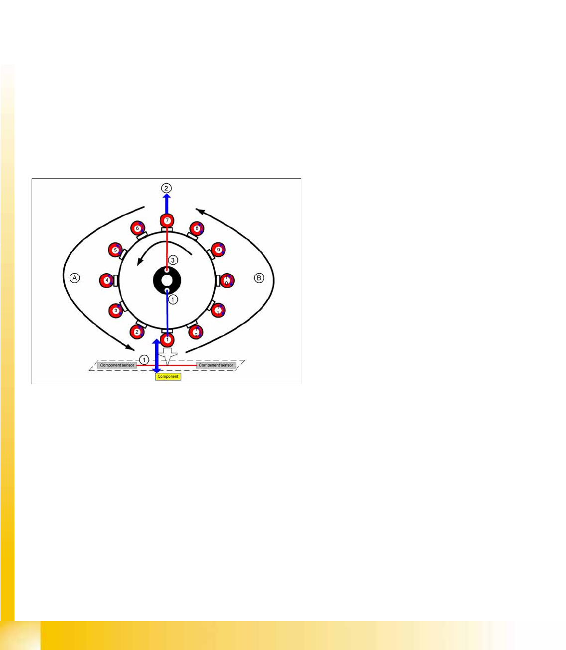
8.4.7 Procedure for Placing Components
Prerequisite: The pickup process and optical centering must have been completed successfully.
1. The gantry moves over the placement position of the 1st component.
2. Vacuum measurement in pickup/place circuit „closed“
3. The Z axis travels down and interrupts the component sensor.
4. The Z position is read out. The nozzle length and component height are calculated using the value
from the Z axis up pickup procedure.
5. Switch on air blast (pressure control valve, depending on programmed placement profile)
6. The Z axis moves up.
7. The component sensor is released and the Z position is read out. The nozzle length is calculated
using the value from the Z axis down (reference value) pickup procedure. The component is placed.
8. The valve for the segment 1 valve terminal is switched off.
9. A vacuum check is performed when the Z axis is in the top position.
10. The star is rotated and more components are placed.
11. Segment 1 is rotated by the DP drive into the pickup position for the next component (area A or B).
12. Once all 12 components have been placed, the placement process has finished.
Legend
1. Vacuum measurement pickup/place circuit
2. Optical centering SIPLACE Vision
3. Vacuum measurement hold circuit
A/B: Rotate the nozzle for the next component into
the correct pickup angle.