00196044-05 - sg x und x4i fse_en.pdf - 第222页
Gantry Track Signals and Zero Pulse C hecking the Zero Pulse Signal S tudent Guide (FSE) SI PL ACE X Series and X4I Gantry Edition 01/2009 EN 222 6.4 T rack Signals and Zero Pulse 6.4.1 Checking the Zero Pulse Signal The…
Gantry
Mechanical Adjustment of the Incremental Encoder Settings
Student Guide (FSE) SIPLACE X Series and X4I
Edition 01/2009 EN Gantry
221
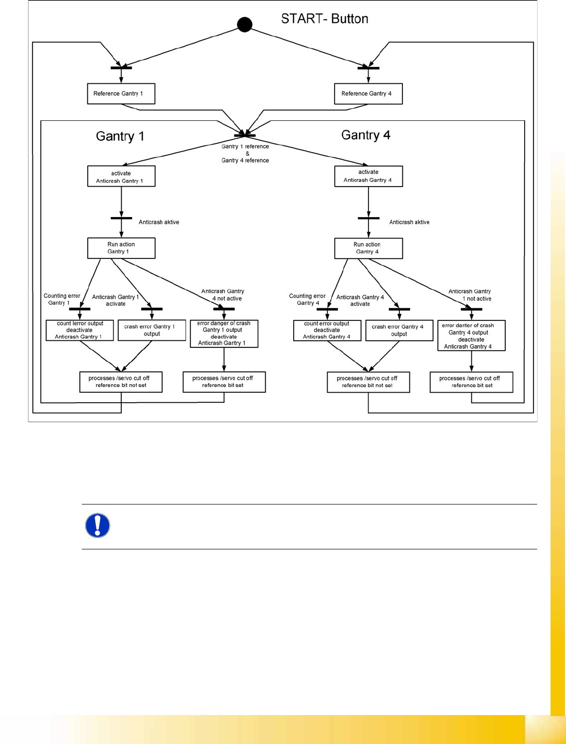
6.3.3.5 Anticrash Function
6-11: Example of the anticrash function sequence in placement area 1
6.3.4 Mechanical Adjustment of the Incremental Encoder
The incremental encoders (read units) on the X and Y axis are adjusted mechanically to a distance of
0.4 mm +/- 0.1 mm to the incremental scale.
After this adjustment of the incremental encoder you have to check the zero pulse and track signals.
NOTE:
To set this distance, use one or more feeler gauges (small plastic disks) with a total thickness
of 0.4 mm.
Gantry
Track Signals and Zero Pulse Checking the Zero Pulse Signal
Student Guide (FSE) SIPLACE X Series and X4I
Gantry Edition 01/2009 EN
222
6.4 Track Signals and Zero Pulse
6.4.1 Checking the Zero Pulse Signal
The zero pulse must be reliably and clearly recognized by the read head. To ensure this, you can check
both the analog and the digital zero pulse. Electronically controlled settings can not be performed on the
incremental length measurement system.
See also:
J
4.4.1.2 Zero Pulse at the Track Signal Encoder [
J
131]
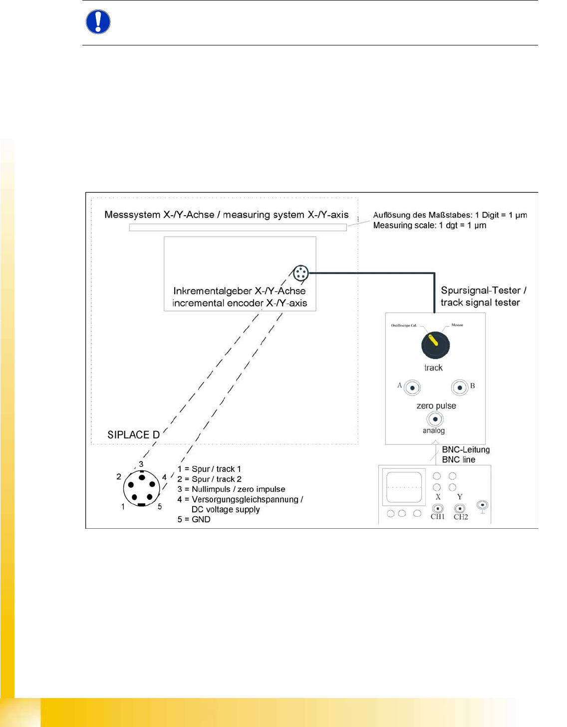
6.4.1.1 Measuring the Analog Zero Pulse Signal
6-12: Measurement procedure for checking the analog zero pulse and the analog track signals
NOTE:
Since 2007 a new read head is fitted. A larger measuring window allows you to reliably
compensate contaminants on the incremental scale (up to approx. 2.5 mm).
Gantry
Checking the Zero Pulse Signal Track Signals and Zero Pulse
Student Guide (FSE) SIPLACE X Series and X4I
Edition 01/2009 EN Gantry
223
Measurement Procedure
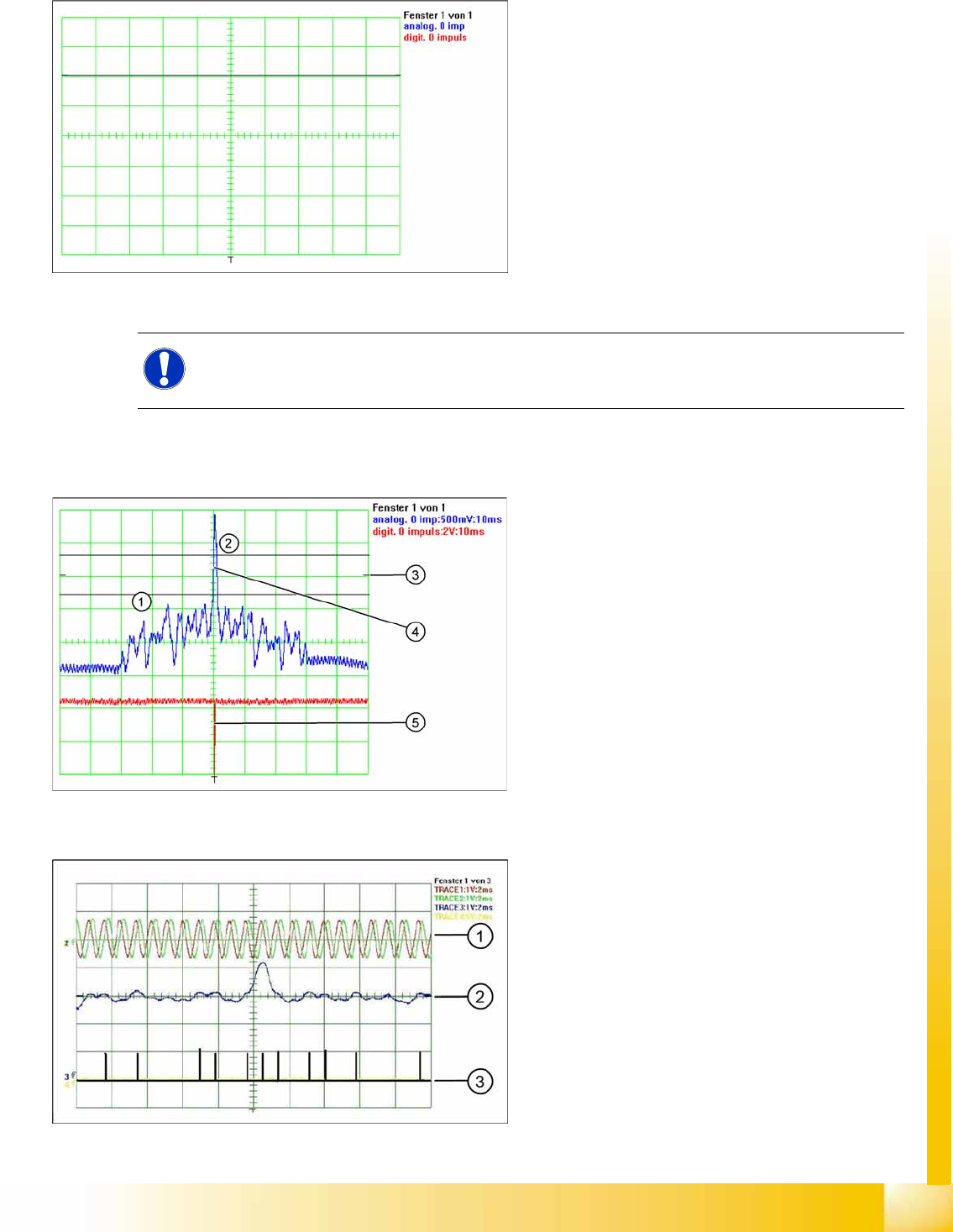
X Move the gantry manually over the zero pulse (see instructions or description of zero pulse search).
X The following picture should appear on the oscilloscope.
6-13: Measuring the initial zero pulse position
X Connect the measurement tester to the
incremental encoder.
X Main switch
ON
X Connect the oscilloscope to the measurement
tester.
X Set the measurement adapter to
Calibrate
oscilloscope
and position the signal at the top,
center of the screen.
NOTE:
When the gantry is positioned at the hardware stop, an area of 25mm begins, in which no zero
pulse search is permitted. Check the first zero pulse after this area, on the incremental scale.
6-14: Correctly adjusted read unit
Legend
1. There should be no interference pulse in the
tolerance space of - 0.3 V.
2. The analog zero pulse must overshoot the
switching threshold by more then 0.3V.
3. Initial position
4. Analog zero pulse
5. Digital zero pulse
6-15: Incorrectly adjusted read unit or contaminated zero pulse
Legend
1. Analog track signal A and B
2. Analog zero pulse
3. Digital zero pulse