00196044-05 - sg x und x4i fse_en.pdf - 第109页
Communication and Control CAN Bus Structure CAN Bus S tudent Guide (FSE) SIPL ACE X Series and X4I Edition 01/2009 EN Communication and Control 109 4.3.3.5 CAN-Bus Concept with One Wi re Bus for SIPLACE X4I As the name i…
Communication and Control
CAN Bus CAN Bus Structure
Student Guide (FSE) SIPLACE X Series and X4I
Communication and Control Edition 01/2009 EN
108
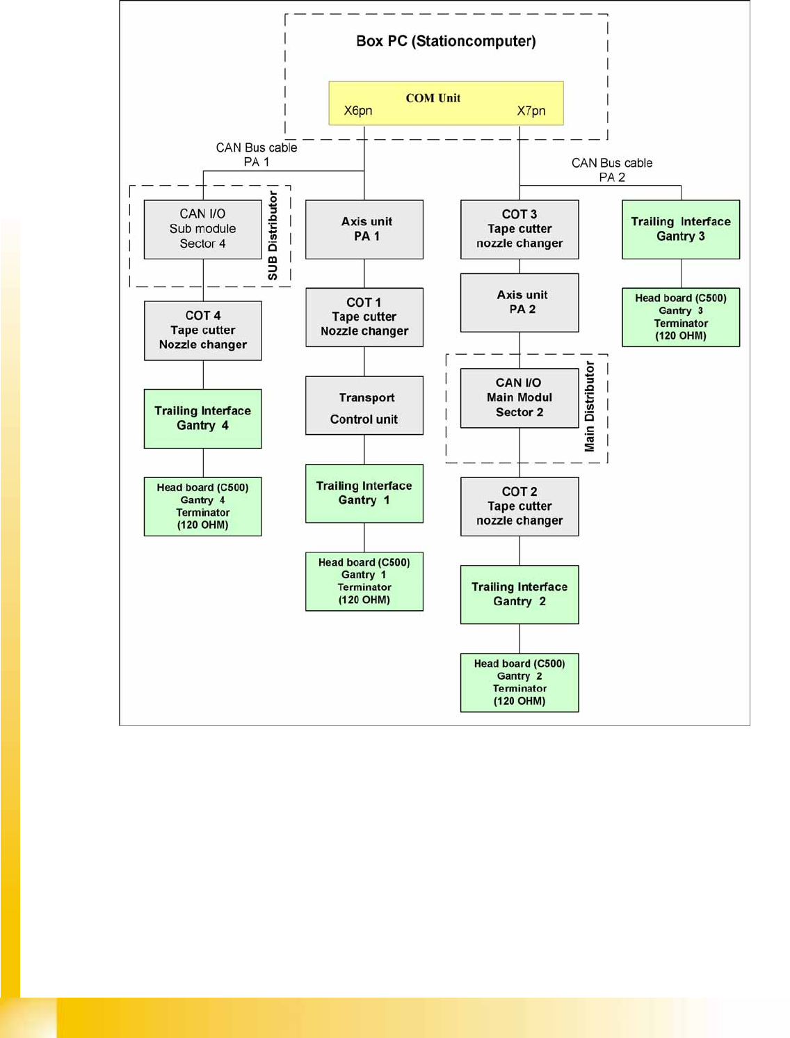
4.3.3.4 CAN Bus Concept Siplace X4I
4-19: CAN Bus overview SIPLACE X4I
The placement machine SIPLACE X4I uses a bus system with 1 Mbit/s transmission rate. The bus
system begins at the communication board and is split in 2 paths. Every path is terminated by a 120 ohm
terminator on the head board at the individual placement head.
Communication and Control
CAN Bus Structure CAN Bus
Student Guide (FSE) SIPLACE X Series and X4I
Edition 01/2009 EN Communication and Control
109
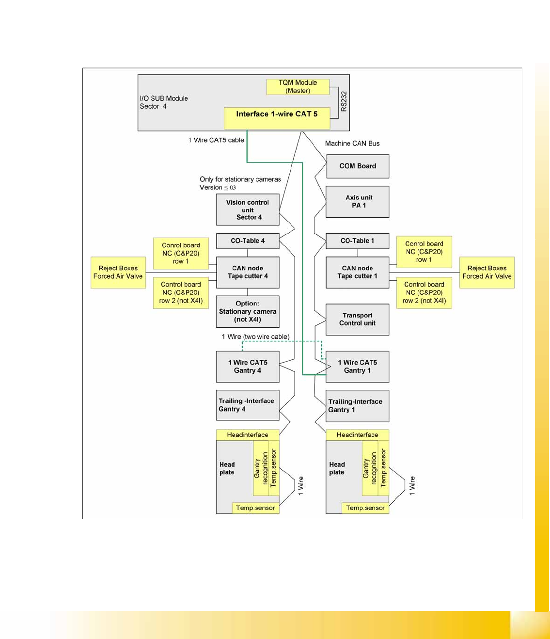
4.3.3.5 CAN-Bus Concept with One Wire Bus for SIPLACE X4I
As the name indicates, the data are transferred (serial transfer) via a single wire, to the relevant
subsystem. The one wire bus system is used for processes where time is not a critical factor and can be
realized as a single master bus with "any number" of nodes. In the SIPLACE X machine, the one wire
bus is integrated into a separate CAT5 cable, which leads through the machine, from the main or
subdistributor to the trailing interface. The master device for the one wire bus is installed on the main
and subdistributors. A kind of switch is located on the other units which require the one wire system (see
figure below). This switch opens and closes the communication path.
Components controlled with the one wire bus system:
Temperature sensors
Gantry recognition (CFK02, CFK04, CFK06)
4-20: Machine CAN Bus overview - SIPLACE X4I
CAT5 (category) - a twisted pair cable for signal transfer.
Communication and Control
CAN Bus CAN Bus Structure
Student Guide (FSE) SIPLACE X Series and X4I
Communication and Control Edition 01/2009 EN
110
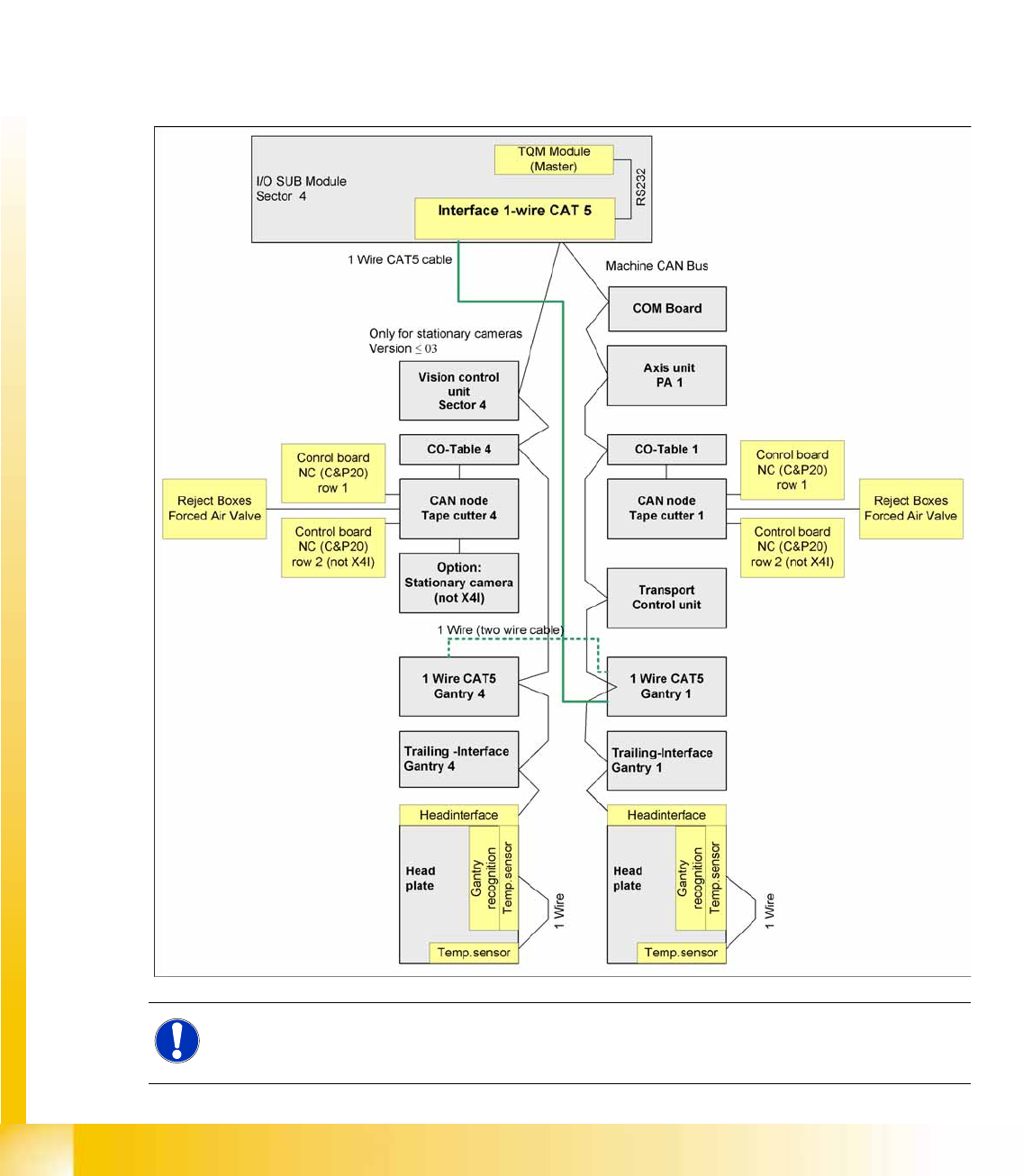
4.3.3.6 CAN-Bus Concept with One Wire Bus e.g. SiplaceX3
The SIPLACE HF/HF3 placement machine uses an additional bus system with the SW 505, which is
integrated into the CAN Bus cable --> One Wire Bus. In the SIPLACE X machine, the one wire bus is
integrated into a separate CAT5 cable, which leads through the machine, from the main or subdistributor
to the trailing interface. The master device for the one wire bus is installed on the main and
subdistributors. A kind of switch is located on the other units which require the one wire system (see
figure below). This switch opens and closes the communication path.
Components controlled with the one wire bus system:
Temperature sensors
Gantry recognition (CFK02, CFK04, CFK06)
One wire overview at an X3 – PA1 with CAN node module
NOTE:
After introduction of the CAN node module, the one wire bus is now only needed to check the
temperatures sensors.