00196044-05 - sg x und x4i fse_en.pdf - 第141页
Communication and Control One Wire Bus - Structure One Wire Bus S tudent Guide (FSE) SIPL ACE X Series and X4I Edition 01/2009 EN Communication and Control 141 4.5.1.2 One Wire Bus in the SIPLACE X 4-43: Overview of one …
Communication and Control
One Wire Bus One Wire Bus - Structure
Student Guide (FSE) SIPLACE X Series and X4I
Communication and Control Edition 01/2009 EN
140
4.5 One Wire Bus
The one wire bus in the SIPLACE X4I is used for requests between the temperature sensors and the
head plates and for reading out the gantry type. The nozzle changer control and sensor requests for the
reject bin are established via a so-called CAN node (see Chapter Component Handling).
Tasks:
1. 2 temperature sensors per gantry (fixed to the head plate).
2. Storage of gantry identification on an EEPROM.
A differentiation is made between plate gantry CFK-02, Design To Cost (DTC) gantry CFK-04 and
CFK 06 gantry. This means that the machine database loaded for the dynamic parameters of the
main axis differs according to the gantry type concerned.
4.5.1 One Wire Bus - Structure
As the name indicates, the data are transferred (serial transfer) via a single wire, to the relevant
subsystem. The one wire bus system is used for processes where time is not a critical factor and can be
realized as a single master bus with „any number“ of slaves (stations).
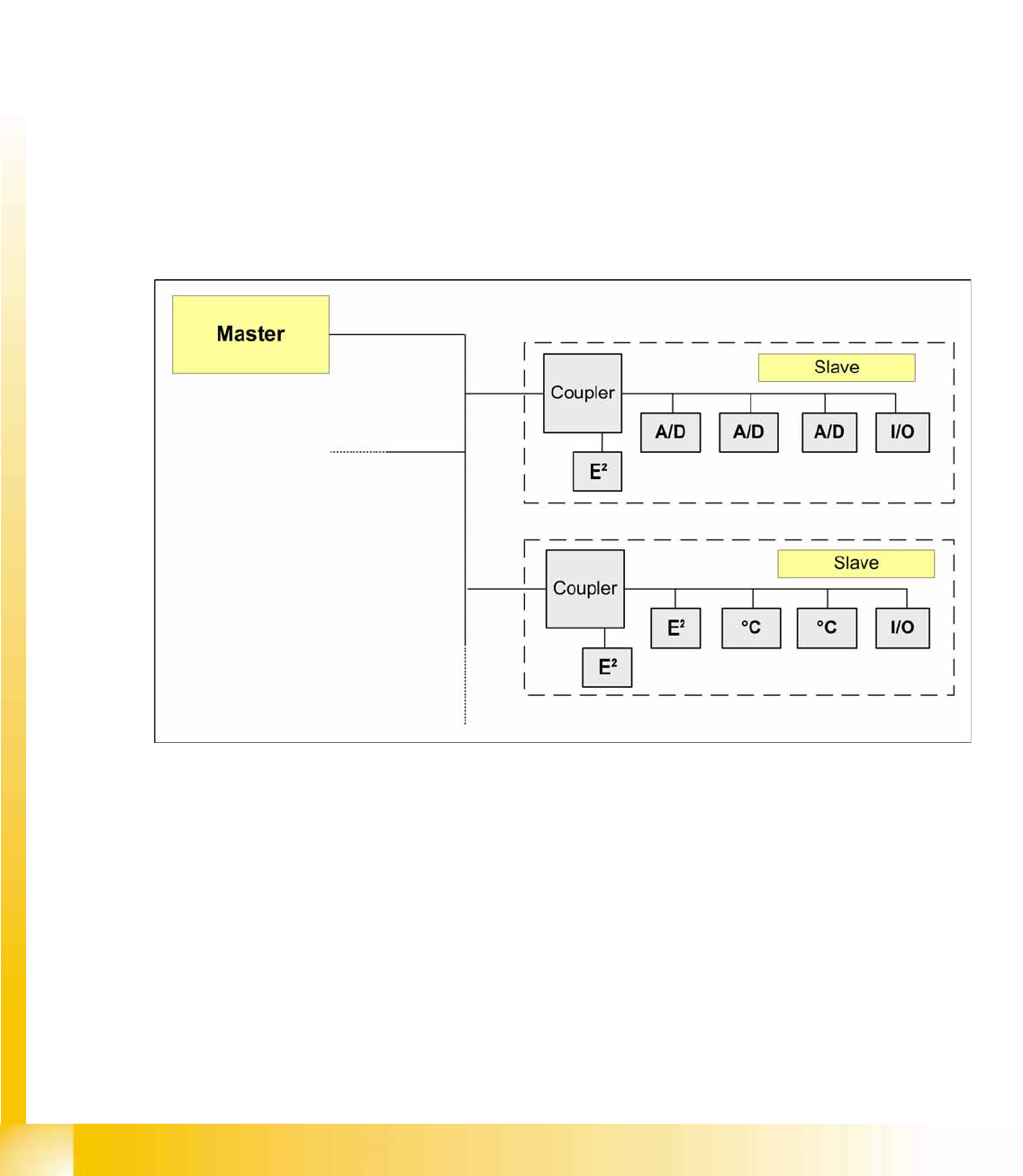
4.5.1.1 Basic Structure
4-42: One wire bus principle
The one wire bus system consists in principle of a master with EEPROM (control unit), which controls
the various submodules such as A/D converters, EEPROM, temperature and I/O modules. Each
communication branch is equipped with an upstream coupler, which opens the branch for data transfer..
Communication and Control
One Wire Bus - Structure One Wire Bus
Student Guide (FSE) SIPLACE X Series and X4I
Edition 01/2009 EN Communication and Control
141
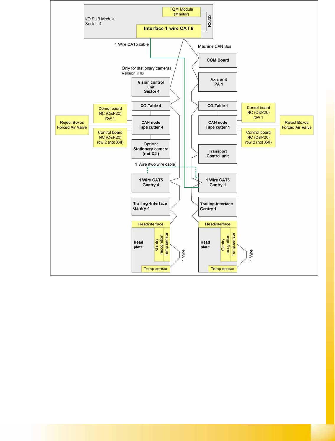
4.5.1.2 One Wire Bus in the SIPLACE X
4-43: Overview of one wire subsystems e.g. PA1 on the SIPLACE X4I
In the SIPLACE X4I machine, the one wire bus is integrated via a separate CAT5 cable, which leads
from the main or subdistributor up to the trailing interface. The one wire bus is run through the trailing
cable from the trailing interface up to the head interface. This means that the cable structure is different
and only the temperature sensors are still monitored. The temperature values are used to calculate the
relevant offset values for placement accuracy.
Communication and Control
One Wire Bus One Wire Bus - Structure
Student Guide (FSE) SIPLACE X Series and X4I
Communication and Control Edition 01/2009 EN
142
4.5.1.3 Function Description
When the machine is switched on, each one wire bus is assigned a fixed CAN ID.
One wire in PA1 --> CAN ID:
07d0
One wire in PA2 --> CAN ID:
07c0
During initialization of the bus system, each station registers with the master, after which the bus is ready
for operation.
In the non operative mode, the voltage level is 5 V on the one wire bus.
A repeat initialization can be performed with the CACCIA tool (see Function Control and Troubleshooting
for Service Work).
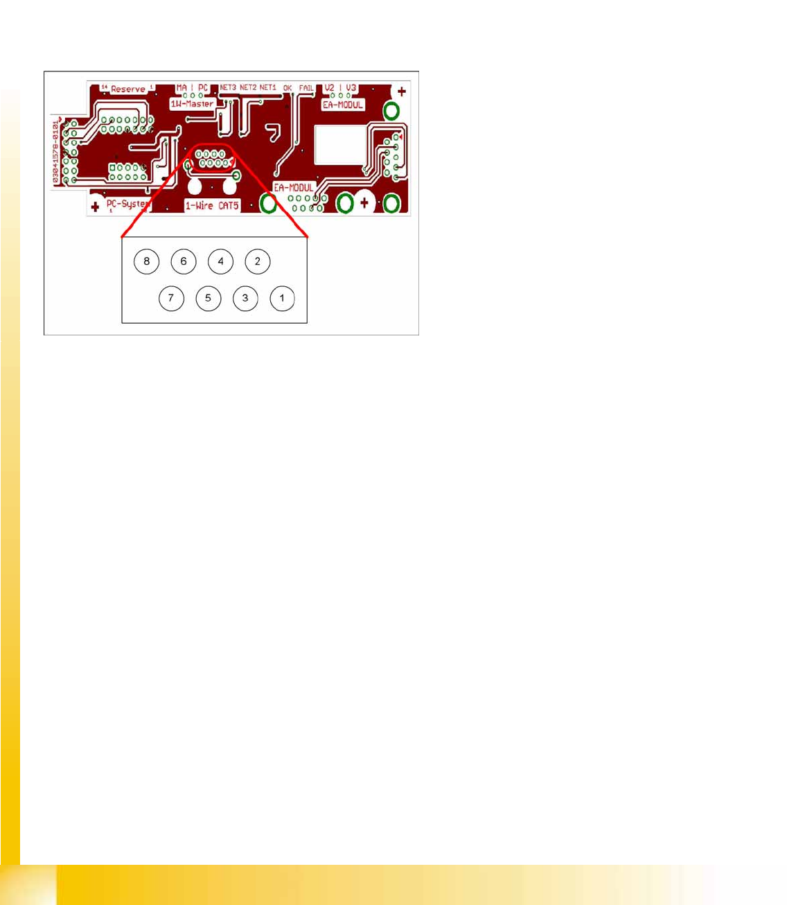
4-44: Interface 1-Wire CAT5
Legend
1. NC row 1 gantry 1/3
2. NC row 2 gantry 1/3
3. Temperature sensors gantry 1
4. Temperature sensors gantry 4
5. NC row 1 gantry 2/4
6. NC row 2 gantry 2/4
7. 24 V
8. GND
For initial analysis, the 5 V level can be measured
at the 1-Wire-CAT5 connector of the interface.
The 24 V at pin 8 can be measured at the old 1-
Wire and serves as voltage supply for the nozzle
changers. The 24 V are fed into the 1-Wire
distributor. However, this is not used at the
interface.