00196044-05 - sg x und x4i fse_en.pdf - 第459页
Modular Conveyor Light Barrier Functions in Input, Interm edi ate and Output Conveyors Conveyor Settings S tudent Guide (FSE) SIPL ACE X Series and X4I Edition 01/2009 EN Modular Conveyor 459 1 1.3.6 Light Barrier Functi…
Modular Conveyor
Conveyor Settings Light Barrier Function in the Placement Area
Student Guide (FSE) SIPLACE X Series and X4I
Modular Conveyor Edition 01/2009 EN
458
11.3.5 Light Barrier Function in the Placement Area
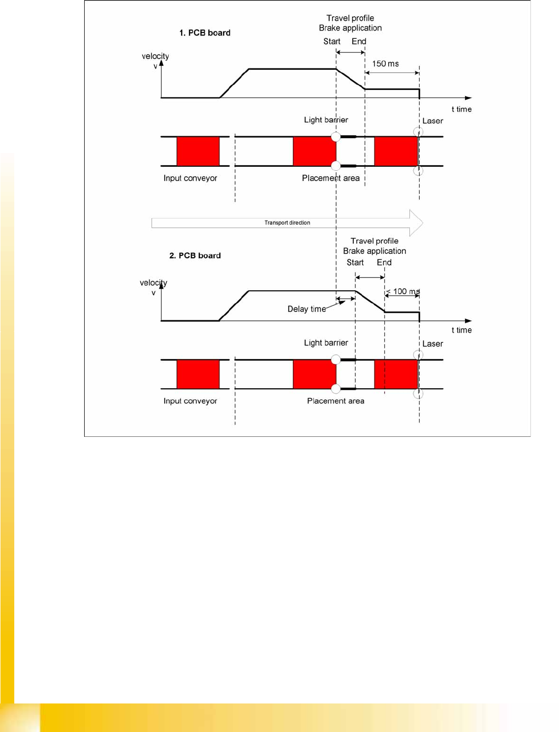
11-17: Diagrams PCB braking
Function:
Switch on the laser light barrier.
Starting the board braking procedure.
The light barrier recognizes the board and the software automatically teaches the creep speed for the
board. Once the travel profile for braking the PCB has begun (on time), the PCB will be reliably stopped
at the laser light barrier, after a maximum of 100ms.
Due to the automatic teaching at the beginning of the travel profile, the stopper position is always
reached in a constant time, irrespective of the board weight. The transport time remains constant.

Modular Conveyor
Light Barrier Functions in Input, Intermediate and Output Conveyors Conveyor Settings
Student Guide (FSE) SIPLACE X Series and X4I
Edition 01/2009 EN Modular Conveyor
459
11.3.6 Light Barrier Functions in Input, Intermediate and Output Conveyors
Function:
Recognizing and stopping the PCB boards.
PCB monitoring in the input conveyer, meaning that
if a PCB is recognized in the input conveyer, this PCB will appear on the station GUI and the machine
will close the conveyor interface to the previous station. When using boards with cutouts, the light
barrier signal may extinguish and the interface to the upstream station may be opened although the
board has stopped. Then the next PCB would move into the input conveyer with the PCB still lying
in the input conveyer. The board monitoring function moves the board backwards and then forwards
again, until the light barrier switches.
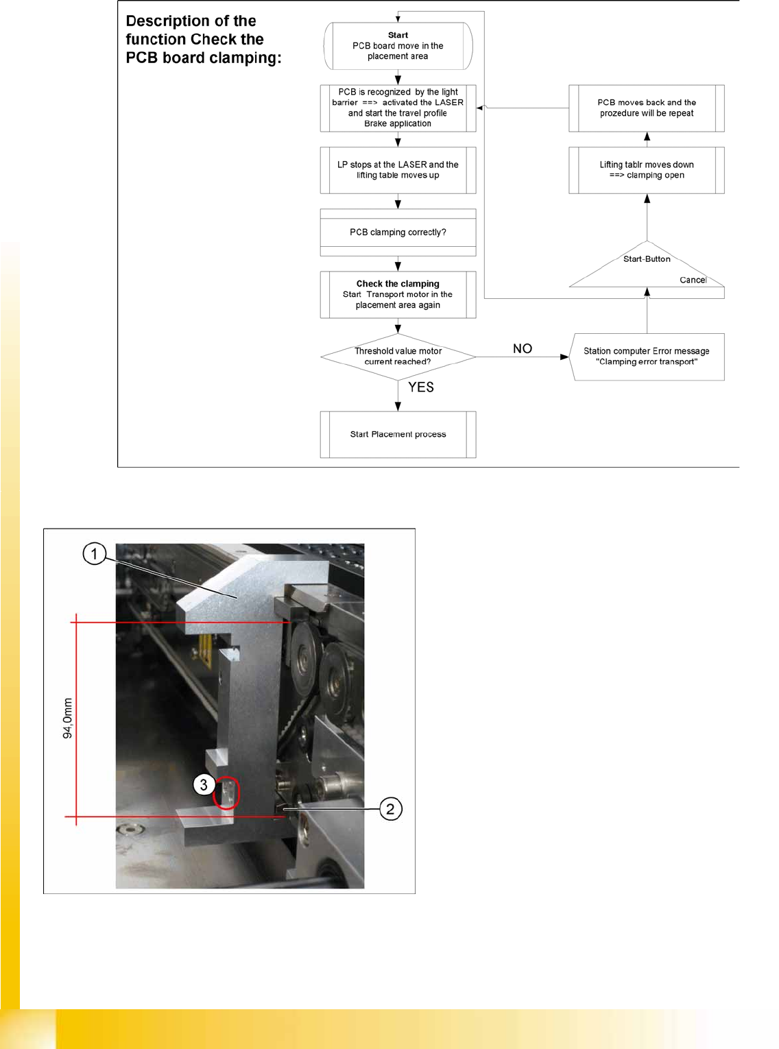
11.3.7 Board Clamping Functions
Function Description:
The PCB moves into the placement area, it is recognized by the light barrier, stops at the laser and
the lifting table moves up.
Check PCB clamping: The transport motor in the placement area start again. If the PCB is clamped
correctly, the motor current will exceed a defined threshold value. Once the board has been correctly
clamped into place, the placement process will begin.
If this threshold is not reached, the system assumes that the board is on its way to the intermediate
or output conveyor and has therefore not been correctly clamped into place.
The station computer will issue the message "PCB not correctly clamped PA1 (PA2)". The process
can be repeated by pressing the "start button".
The lifting table will move downwards, the board will be transported back and the stopper position
will be approached again.
NOTE:
The check whether a PCB is clamping correctly, is controlled with a motor current check of the
transport motor if the PCB board is clamped (Lifting table up). To check the function you could
put a distance plate under the conveyor side, so that the lifting table can not move to the upper
position.
The check is not performed if the option "Vacuum Tooling" is installed.
Modular Conveyor
Conveyor Settings Board Clamping Functions
Student Guide (FSE) SIPLACE X Series and X4I
Modular Conveyor Edition 01/2009 EN
460
11.3.7.1 Setting Board Clamping
11-18: Setting the actuator
Legend
1. Gauge [00369202-01]
2. Actuator
3. Drilling, for fixing the actuator screws, when
the gauge is fitted
If the conveyor control issues the error
Clamping
error transport
, check the distance from the lifting
table actuator to the top edge of the conveyor belt.
Use the setting gauge to check and set the
actuator. The distance from the clamping actuator
(lifting table) to the top edge of the belt should be
94.0 mm at all four contact points. (see diagram)