00196044-05 - sg x und x4i fse_en.pdf - 第163页
Communication and Control Reading the Board IDs out of the EEPROM Board IDs S tudent Guide (FSE) SIPL ACE X Series and X4I Edition 01/2009 EN Communication and Control 163 4.6.2.2 Reading and Writing the Board IDs with C…
Communication and Control
Board IDs Reading the Board IDs out of the EEPROM
Student Guide (FSE) SIPLACE X Series and X4I
Communication and Control Edition 01/2009 EN
162
Assembly ID 01 is digital pressure control valve
Assembly ID 02 is analog pressure control valve
4-65: Device number pressure control valve digital C&P20A
NOTE:
The digital pressure control valve (C&P20A) and the analog pressure control valve (Twin head)
do not have a board ID or it is currently 00.
NOTE:
Both pressure control valves will be recognized via a device number. This assembly ID is at
memory cell 14 in the EEPROM.
Communication and Control
Reading the Board IDs out of the EEPROM Board IDs
Student Guide (FSE) SIPLACE X Series and X4I
Edition 01/2009 EN Communication and Control
163
4.6.2.2 Reading and Writing the Board IDs with CAN Commands
X Switch off the machine.
X Connect the service laptop to the machine CAN bus at PA1 and/or PA2.
Make sure that the cable is connected at channel 1 for PA1 and at channel 2 for PA2 of the Kvaser
card.
X Switch on the machine
X Start the
Caccia
software and check the machine configuration in
Caccia
.
X Doubleclick on the
Open Subsystem Control Center
.
X Select
Get Versions
.
All available subsystems will be shown with their firmware versions and their CAN IDs.
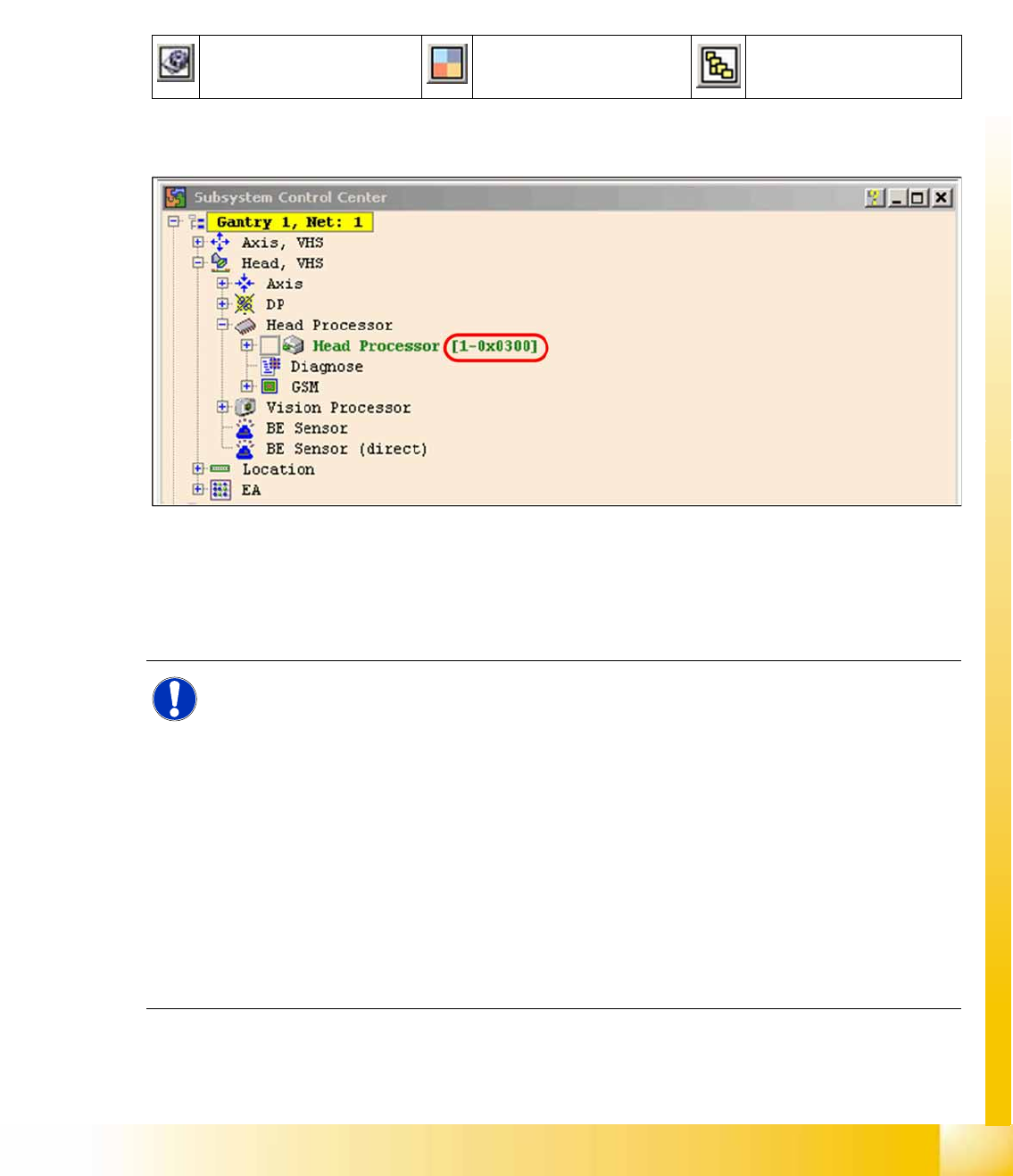
4-66: Subsystem control center
X In the
Subsystem control center
window, search for the subsystem (TQM module), which you want
to access, in order to then use the correct CAN ID in the network window.
X This means, to check the head interface, head adapter and intermediate distributor use the CAN ID
300 for gantry 1 or 308 for gantry 2 and so on.
Change Properties Change Machine
Configuration
Open Subsystem Control
Center
NOTE:
Always use the IDs which are shown in the subsystem control window, when you click on
GET VERSION or ACTIVATE IDs
.
e.g. Head Processor
Gantry 1 -->
300
Gantry 2 -->
308
Gantry 3 -->
310
Gantry 4 -->
318
.
Exception: If you don‘t received a message from a subsystem, so you can try to work with
"Standard ID‘s" e.g.Head processor:
Gantry 1 -->
304
Gantry 2 -->
30c
Gantry 3 -->
314
Gantry 4 -->
31c
,
required when two board IDs are missing.
Communication and Control
Board IDs Reading the Board IDs out of the EEPROM
Student Guide (FSE) SIPLACE X Series and X4I
Communication and Control Edition 01/2009 EN
164
X Perform a BIOS download to the TQM module, so that you are sure that only the BIOS is running.
X Open the network 1 for PA 1 and network 2 to for PA 2.
X With the correct CAN ID and the BIOS commands, you can now write the correct board ID in the
EEPROM.
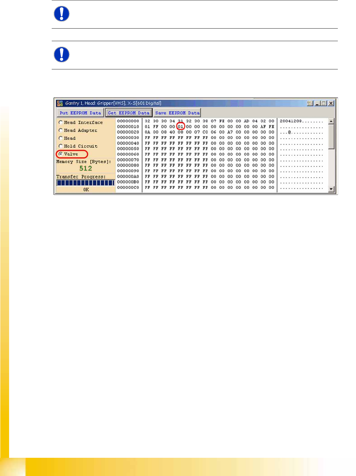
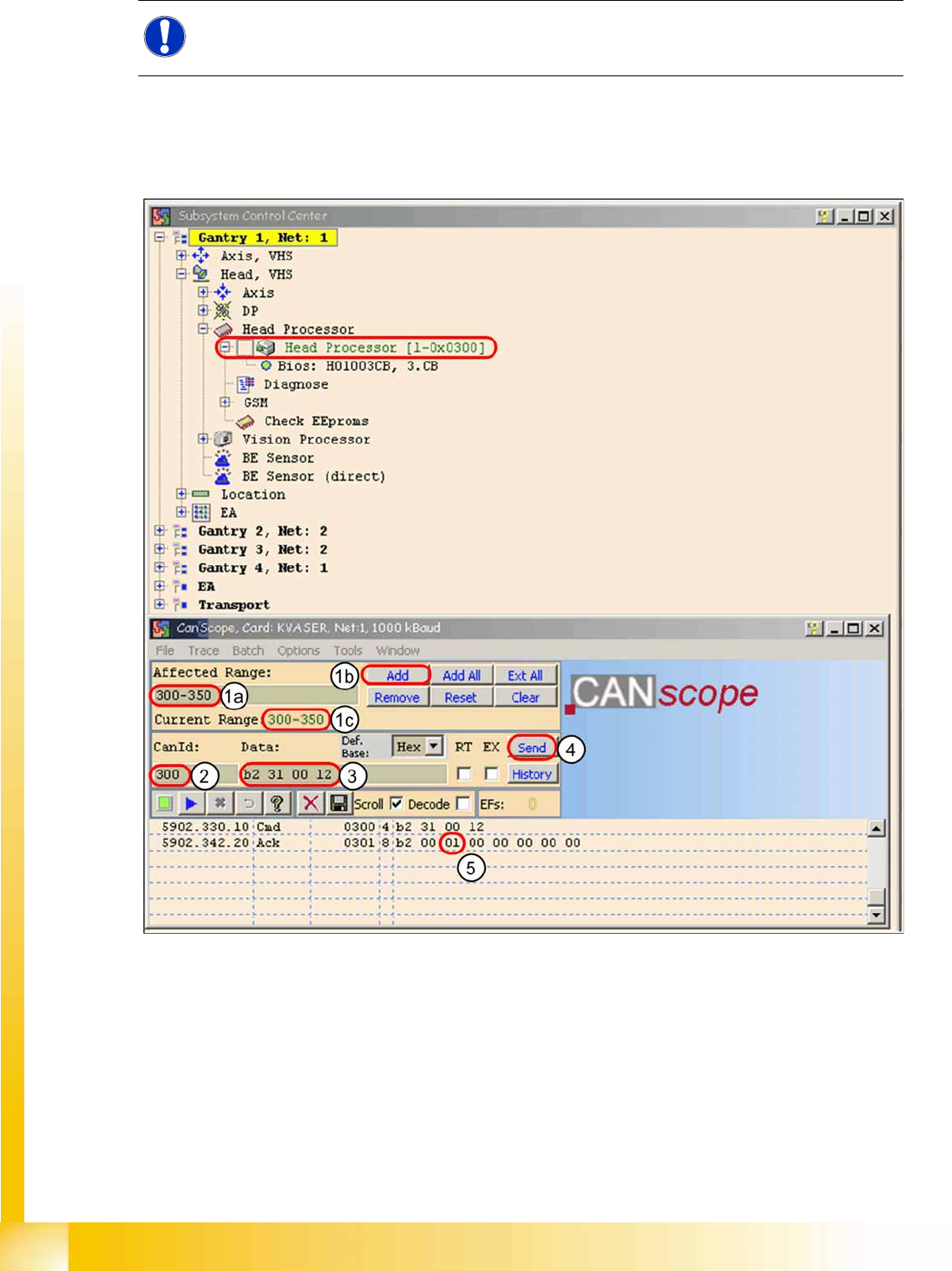
4-67: Read the board type ID Head interface
X (1) Restrict the address range for the CAN ID. Specify the smallest possible range at
Affected Range
, This reduces the number of CAN telegrams shown in the network window.
X Confirm with
Add
X The CAN ID range will now be shown at
Current Range
.
X (2) At
CanID
enter the relevant ID.
X (3) At
Data
enter the CAN command.
Example
B2 31 00 12
b2
--> read EEPROM
31
--> read out from head interface
12
--> Storage location in EEPROM memory in hex
NOTE:
To write the board IDs with CAN commands, make sure that just the BIOS is running on the
TQM module.