00196044-05 - sg x und x4i fse_en.pdf - 第332页
Collect, Pick and Place Head (CPP) Pickup and Placement Cycle for CPP Detailed Standard Pickup Proced ure: Z Axis Down S tudent Guide (FSE) SI PL ACE X Series and X4I Collect, Pick and Place Head (CPP) Edition 01/2 009 E…

Collect, Pick and Place Head (CPP)
Pickup and Placement Cycle For the Next Components Pickup and Placement Cycle for CPP
Student Guide (FSE) SIPLACE X Series and X4I
Edition 01/2009 EN Collect, Pick and Place Head (CPP)
331
8.4.8 Pickup and Placement Cycle For the Next Components
After all the components of the first head cycle have been placed on the board, the gantry axes move
the placement head to the pickup position of the next pickup cycle.
The next pickup cycle is performed for the components.
If necessary the machine performs repair cycles.
8.4.9 Segment with a "Defective Component“
If the optical centering of a component fails (ident. error) or component recognition before placement
fails, the component will not be placed and will remain on the nozzle.
The turning station will still turn this nozzle to the pickup angle of the new component if this segment
is in area A.
If this segment is in pickup position:
The reject procedure will be activated and
the X/Y axes will move to the reject position for this gantry,
The component will be rejected to the reject box below, via air blast
The new component is picked up.
The rejected component will then be placed in a repair run after all the other placement cycles for this
placement head have been performed.
8.4.10 Finishing Board Placement
After placing the last component, the gantry axes move the placement heads to the waiting position.
An optical nozzle scan is performed after the first board or after the relevant board (depending on
the scan parameters).
The SIPLACE placement station activates the conveyor system and moves the board to the
intermediate/output conveyor.
Finally, the SIPLACE placement station sends the number of consumed components (placed and
rejected ones) to the computer with the OIS (Operator Information System).
The OIS (Operator Information System) calculates the placement statistics referring to the
programmed station setup, the programmed panel or the last reset time. This detailed data is used
to optimize the process.
The machine is now ready for the next board.
Collect, Pick and Place Head (CPP)
Pickup and Placement Cycle for CPP Detailed Standard Pickup Procedure: Z Axis Down
Student Guide (FSE) SIPLACE X Series and X4I
Collect, Pick and Place Head (CPP) Edition 01/2009 EN
332
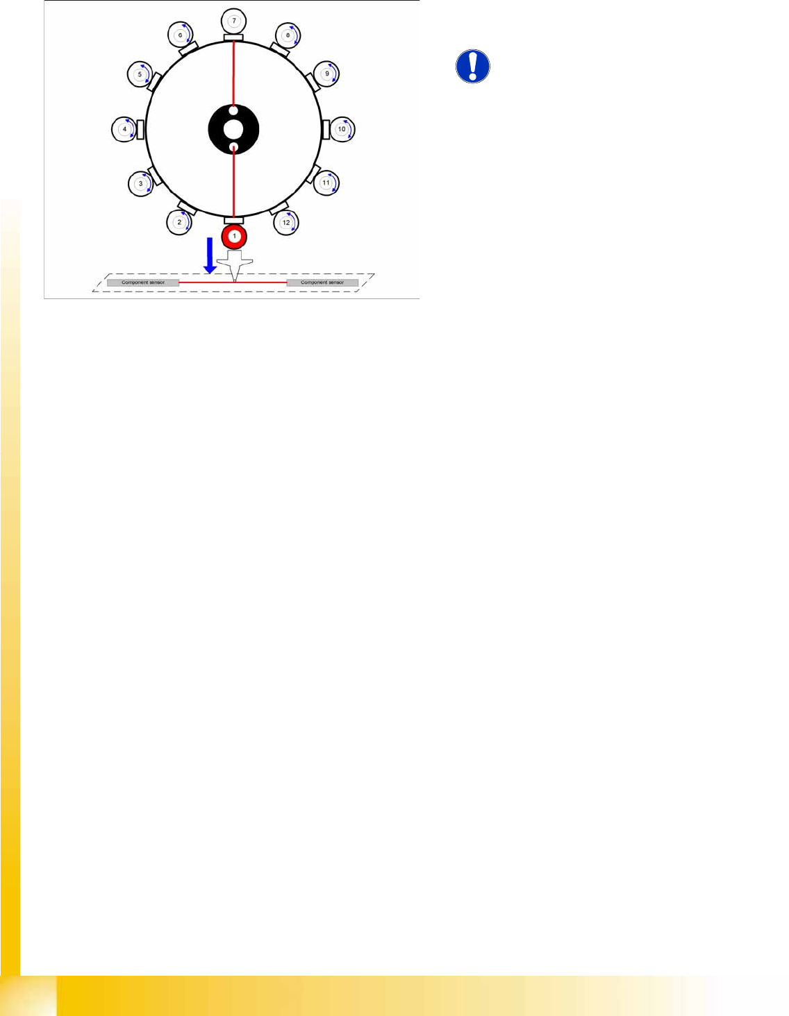
8.4.11 Detailed Standard Pickup Procedure: Z Axis Down
Enables vacuum query: segment open threshold ? YES
Component sensor switches due to Z axis movement:
Measurement value for nozzle length "empty"
Axis controller:
Enable "light barrier down" signal.
LB down switches:
End signal Z axis positioning down
Z axis measurement value for pickup height optimization
8-12: Star position 0°: detailed pickup sequence - Z axis down
Start gantry axes to the pick up position of next
feeder.
NOTE:
The vacuum for the holding circuit of
each segment is switched on via the
valve terminal, just before pickup is
performed. The vacuum is used for
picking up components and mainly
comes from the pressure control valve.
The holding circuit vacuum is only used
to hold the component on the nozzle
during the star rotation.
Start signal for X and Y axes to move to next
feeder.
End signal X, Y axes:
X/Y end position signals available.
Z axis starts:
Z axis starts positioning downwards
End position signal for star axis
Collect, Pick and Place Head (CPP)
Detailed Standard Pickup Procedure: Z Axis Up Pickup and Placement Cycle for CPP
Student Guide (FSE) SIPLACE X Series and X4I
Edition 01/2009 EN Collect, Pick and Place Head (CPP)
333
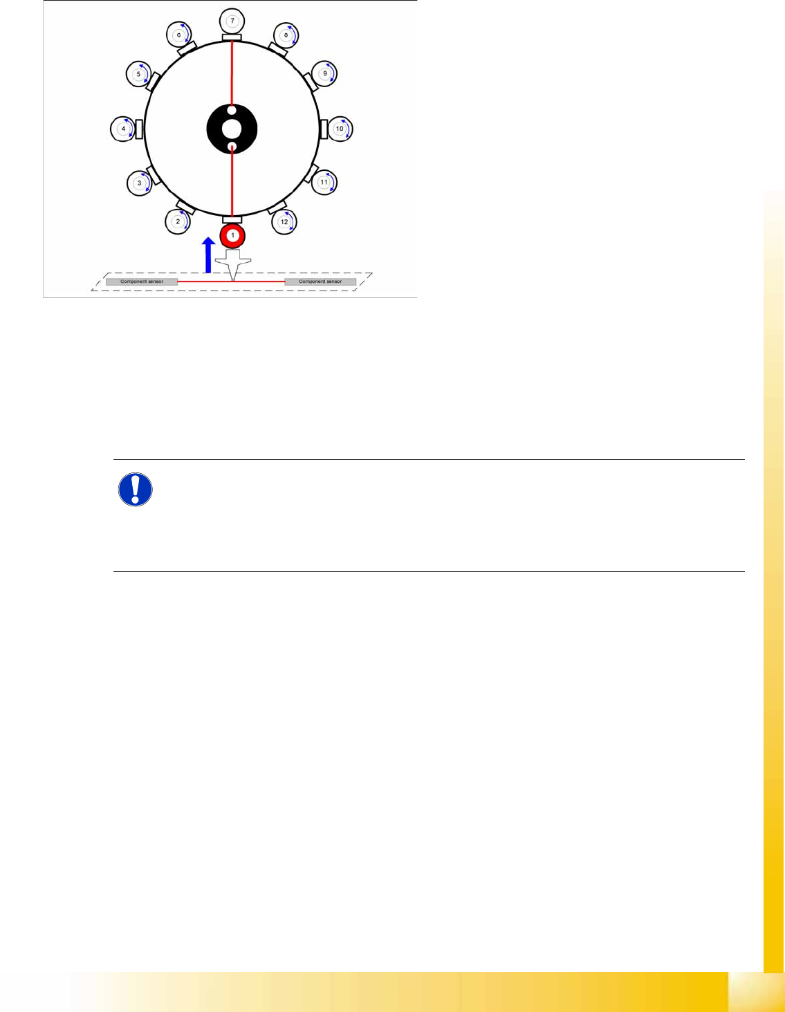
8.4.12 Detailed Standard Pickup Procedure: Z Axis Up
8-13: Detailed pickup procedure: Z Axis Up
LB down switches:
Vacuum Threshold comp. picked reached?
YES
Z axis starts:
Z axis starts positioning upwards
Component sensor switches due to Z axis
movement:
Z axis position value; nozzle length +
comp.height measurement threshold
reached? YES
Z axis position in safety area:
reset light barrier state,
X, Y gantry axes start
start component feeder (communication to
feeder table)
Vacuum query:
Vacuum threshold for holding circuit reached?
YES
Star axis starts.
NOTE:
Since the travel paths for each axis can be calculated and are therefore known, the next action
(e.g. starting the Z axis) is started via position flags. These are sent by the predecessor action
(e.g. star axis). This enables the Z axis to start moving 10 ms earlier (depending on the
definition). It no longer needs to wait for the end position signal from the star axis. The end
position signal is therefore no longer in use.