00196044-05 - sg x und x4i fse_en.pdf - 第133页
Communication and Control Axis Dynamic Basics Axis Control S tudent Guide (FSE) SIPL ACE X Series and X4I Edition 01/2009 EN Communication and Control 133 4-34: Positioning with overshoot into target position During init…
Communication and Control
Axis Control Axis Dynamic Basics
Student Guide (FSE) SIPLACE X Series and X4I
Communication and Control Edition 01/2009 EN
132
4.4.2 Axis Dynamic Basics
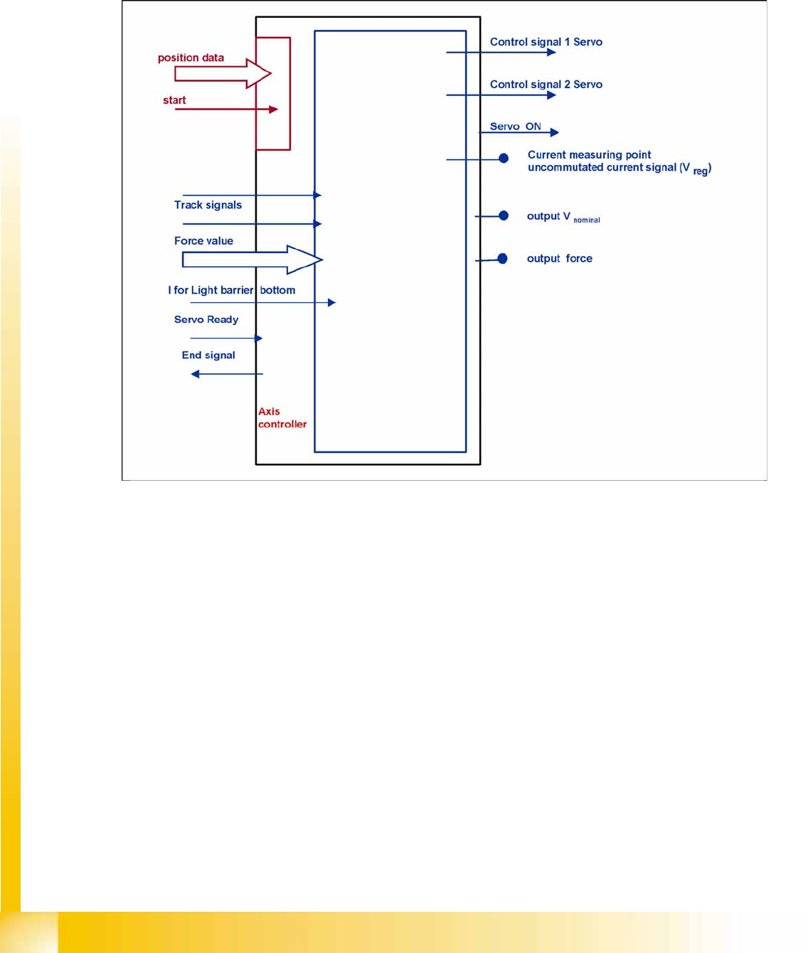
Each axis starts from a position with acceleration a constant speed phase and deceleration should move
the axis into a target position. The dynamic movement of the axis on the SIPLACE machine is regulated
by a digital control system. A powerful digital processor permanently adjusts the axis behavior to each
state of axis dynamic. This means all adjustments for speed (Tacho) and positioning quality (P-gain) at
the servo amplifier are removed. The control signals are different for this new axis control principle.
4-33: Digitally controlled axes for SIPLACE machine
Communication and Control
Axis Dynamic Basics Axis Control
Student Guide (FSE) SIPLACE X Series and X4I
Edition 01/2009 EN Communication and Control
133
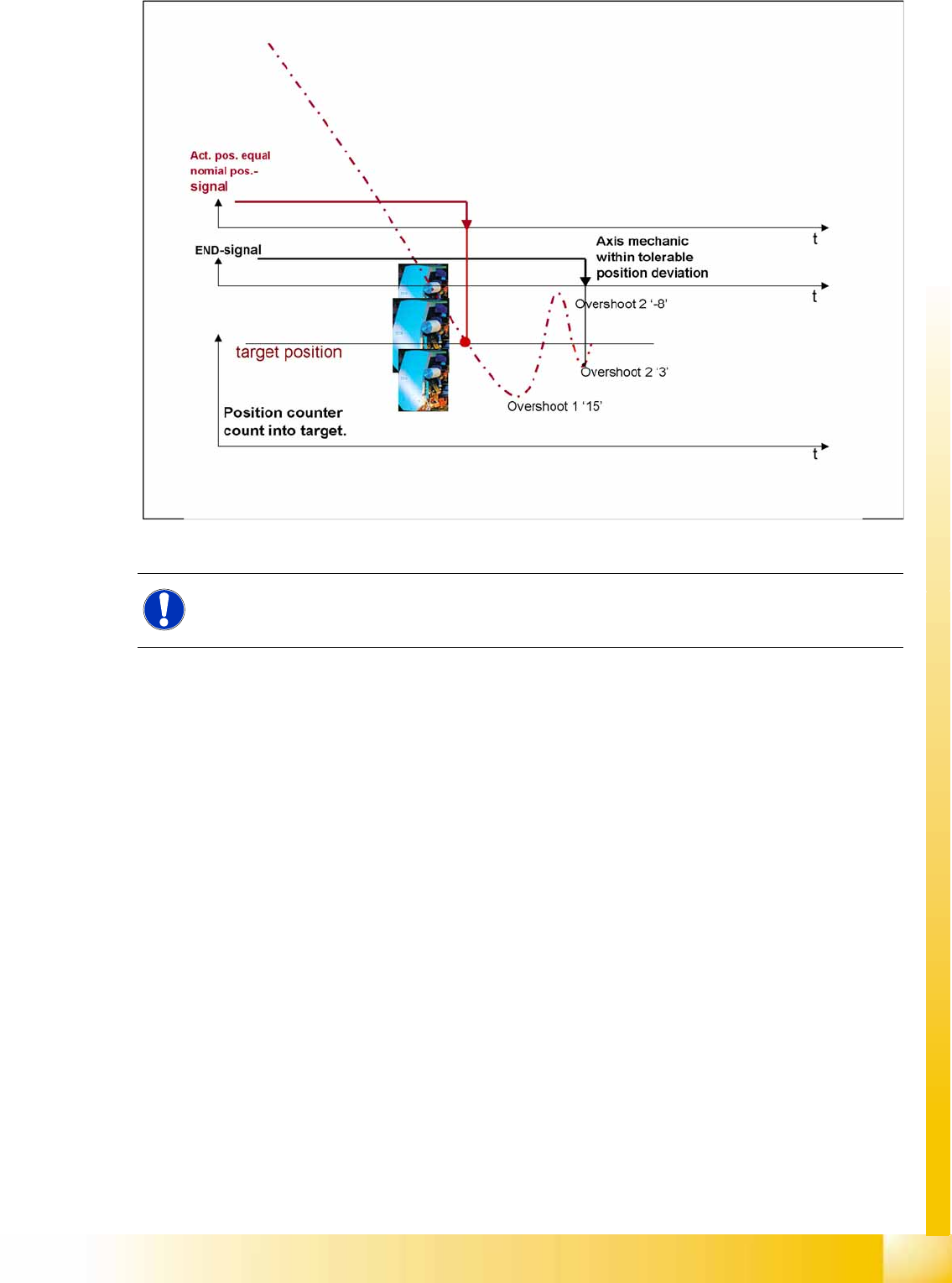
4-34: Positioning with overshoot into target position
During initial Positioning into the target position, the actual equals target position signal triggers an
overshoot count in the axis test box (SAT) for the position deviation signal.
If the overshoot is greater than the permitted position deviation for this axis, the end position signal will
be delayed until the deviation has been regulated so that it is within the permitted range.
NOTE:
The position deviation signal shows the positioning quality of an axis movement in position.
Communication and Control
Axis Control Axis Dynamic Basics
Student Guide (FSE) SIPLACE X Series and X4I
Communication and Control Edition 01/2009 EN
134
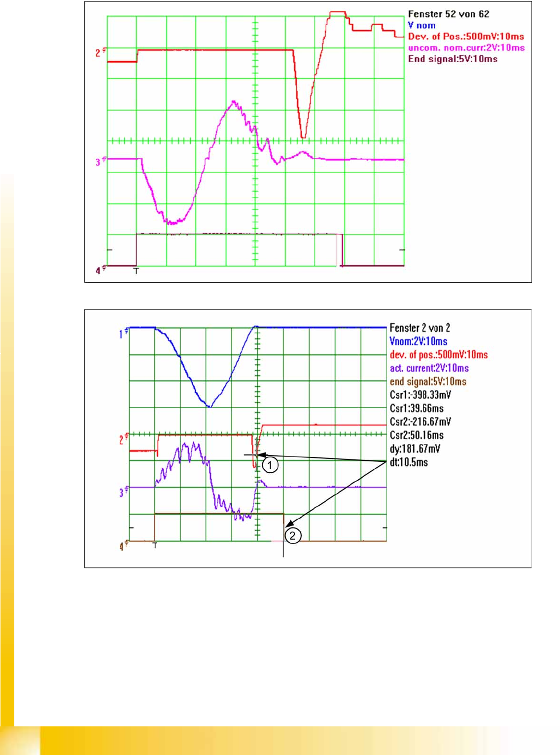
4-35: The 2nd overshoot sets the end signal
4-36: Positioning with asymptotic approach after the initial, excessive overshoot
The positioning shown above demonstrates an excessive overshoot. However, no other overshoot, for
which an end signal could be issued, will occur during this positioning run. The axis controller has a
’backup strategy’ - When the permitted position deviation range is reached, a 10ms timer is started. 10
ms after entering the permissible range (here 5 digits (1)) the timer triggers the end position signal (2).
The permitted range must not be left during this period.
The system generates an uncommutated current target signal from all motor current target signals for
assessment of the axis dynamics by a service technician. This signal gives information about the
mechanical friction in the axis system. This can be measured on the adapter board of the axis test box
or at the Vreg output of the SIPLACE axis tester (SAT).