00196044-05 - sg x und x4i fse_en.pdf - 第270页
C&P20A Pickup and Placement Cycle for C&P20A Placing Component 11 S tudent Guide (FSE) SI PL ACE X Series and X4I C&P20A Edition 01/2009 EN 270 7.4.17 Placing Compon ent 1 1 7.4.18 Placing Component 20 7-34: …
C&P20A
Component Sensor Checks Segment 1 Pickup and Placement Cycle for C&P20A
Student Guide (FSE) SIPLACE X Series and X4I
Edition 01/2009 EN C&P20A
269
7.4.15 Component Sensor Checks Segment 1
See also:
J
7.4.13 Checking the Component Sensor of the Component at Segment 1 [
J
268]
7.4.16 Placing Component 10
7-32: Component sensor checks after placement
Star position 0°
Vision system: Optical centering of component
11
Pickup/placement station: Z axis moves
upwards and sensor checks whether
component has been placed at segment 1.
A : The components previously picked up are
rotated to the centering angle, here.
B : The components are adjusted to their
placement angles.
Vacuum check: whether vacuum has been
switched back on.
NOTE:
The component check by the component sensor is also performed for all other nozzles.
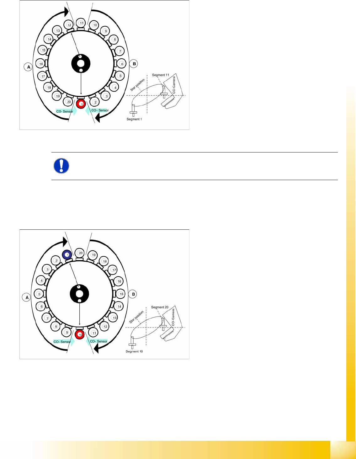
7-33: Placing component 11
Star position 162°
Vision system: Optical centering of component
20
Pickup/placement station: Place component
10 (here: red)
At the next step Vision system have to center
optically the component at segment 1 on the
other gantry. blue).
Component sensor: Checks before
placement; if component is present on nozzle
/ after placement; if the component has been
placed. (see Sections (7.4.13 Checking the
Component Sensor of the Component at Seg-
ment 1
J
268 ) to (7.4.15 Component Sen-
sor Checks Segment 1 g2269 ) )
A : The components previously picked up are
rotated to the centering angle, here.
B : The components are adjusted to their
placement angles.
C&P20A
Pickup and Placement Cycle for C&P20A Placing Component 11
Student Guide (FSE) SIPLACE X Series and X4I
C&P20A Edition 01/2009 EN
270
7.4.17 Placing Component 11
7.4.18 Placing Component 20
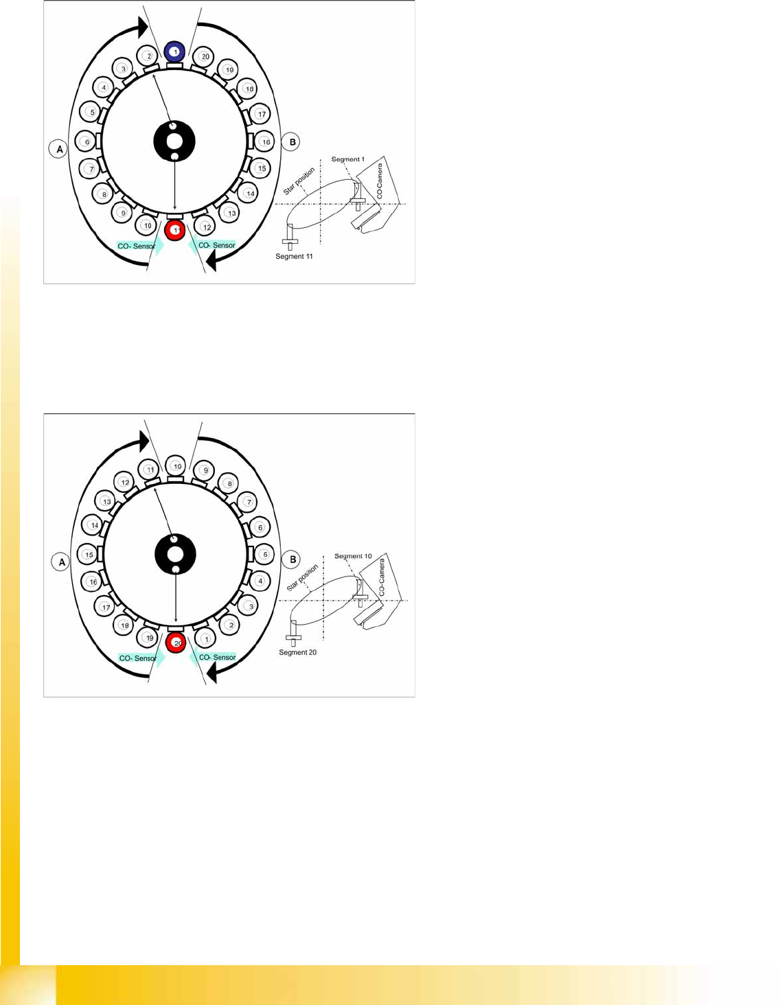
7-34: Placing component 11
Star position 180°
Vision system: Optical centering of component
1 on other gantry (here: blue)
Pickup/placement station: Place component
11 (here: red)
Component sensor: Checks before
placement; if component is present on nozzle
/ after placement; if the component has been
placed. (see Sections (7.4.13 Checking the
Component Sensor of the Component at Seg-
ment 1
J
268 ) to (7.4.15 Component Sen-
sor Checks Segment 1 g2269 ) )
A : The components previously picked up are
rotated to the centering angle, here.
B : The components are adjusted to their
placement angles.
7-35: Placing component 11
Star position 342°
Vision system: Optical centering of component
10 on other gantry (here: blue).
Pickup/placement station: Place component
20 (here: red)
Component sensor: Checks before
placement; if component is present on nozzle
/ after placement; if the component has been
placed. (see Sections (7.4.13 Checking the
Component Sensor of the Component at Seg-
ment 1
J
268 ) to (7.4.15 Component Sen-
sor Checks Segment 1 g2269 ) )
A : The components previously picked up are
rotated to the centering angle, here.
B : The components are adjusted to their
placement angles.
Synchronization: After the 20th component
this gantry Y axis controller will enable the
other gantry Y axis to move to 1st placement
position.

C&P20A
Pickup and Placement Cycle For the Next Components Pickup and Placement Cycle for C&P20A
Student Guide (FSE) SIPLACE X Series and X4I
Edition 01/2009 EN C&P20A
271
7.4.19 Pickup and Placement Cycle For the Next Components
After all the components of the first head cycle have been placed on the board, the gantry axes move
the placement head to the pickup position of the next pickup cycle.
The next pickup cycle is performed for components 21 - 40.
The subsequent pickup cycles follow the same procedure. If necessary the machine performs repair
cycles.
7.4.20 Segment with a "Defective Component“
If the optical centering of a component fails (ident. error) or component recognition before placement
fails, the component will not be placed and will remain on the nozzle.
The turning station will still turn this nozzle to the pickup angle of the new component if this segment
is in area A.
If this segment is in pickup position:
The reject procedure will be activated and
the X/Y axes will move to the reject position for this gantry,
The component will be rejected to the reject box below, via air blast
The new component is picked up.
The rejected component will then be placed in a repair run after all the other placement cycles for this
placement head have been performed.
7.4.21 Finishing Board Placement
After placing the last component, the gantry axes move the placement heads to the waiting position.
An optical nozzle scan is performed after the first board or after the relevant board (depending on
the scan parameters).
The SIPLACE placement station activates the conveyor system and moves the board to the
intermediate/output conveyor.
Finally, the SIPLACE placement station sends the number of consumed components (placed and
rejected ones) to the computer with the OIS (Operator Information System).
The OIS (Operator Information System) calculates the placement statistics referring to the
programmed station setup, the programmed panel or the last reset time. This detailed data is used
to optimize the process.
The machine is now ready for the next board.