00196044-05 - sg x und x4i fse_en.pdf - 第177页
Energy and Compressed Air Supply Power supply Power supply S tudent Guide (FSE) SIPL ACE X Series and X4I Edition 01/2009 EN Energy and Compressed Air Supply 177 5.2.4.1 V olt ages at the Main Power Sup ply Assembly Desi…
Energy and Compressed Air Supply
Power supply Power supply
Student Guide (FSE) SIPLACE X Series and X4I
Energy and Compressed Air Supply Edition 01/2009 EN
176
The following work must be performed to adjust the power supply to the country-specific requirements
(see also the conversion instructions for power supplies):
1. Replace the motor protecting switch
2. Replace the power supply cable (country-specific)
3. At the primary end of transformer T1, the terminal connectors (U, V, W) must be reconnected to fulfill
the country-specific voltage requirements.
4. Reconnect the connector on the inrush limitation board transformer.
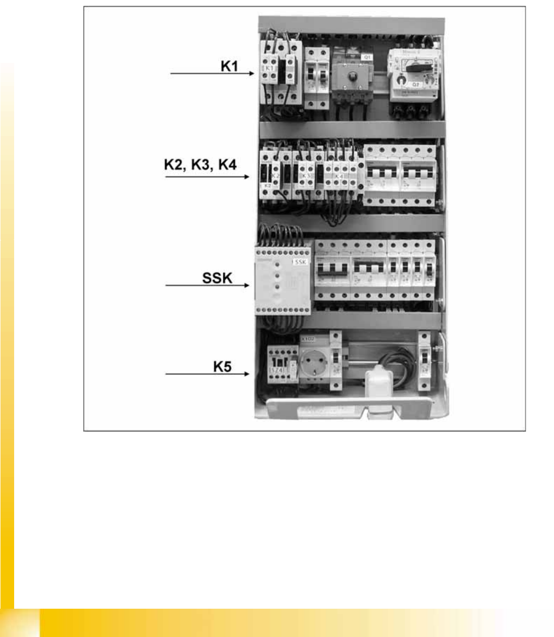
5-5: Main power supply
3 phase alternating power is supplied for operation of the SIPLACE X machines. N is only used for the
service socket. The contacts L1/L2/L3/N/PE are below the main power module. The phase L3 is also
fuse-protected for the server socket, via the F1 fuse.

Energy and Compressed Air Supply
Power supply Power supply
Student Guide (FSE) SIPLACE X Series and X4I
Edition 01/2009 EN Energy and Compressed Air Supply
177
5.2.4.1 Voltages at the Main Power Supply
Assembly Designation Contact Voltages
X100 Main power supply L1, L2, L3 3 x 204 VAC / 3 x 380 VAC
3 x 400 VAC / 3 x 415 VAC
X102 service socket L3, N, PE 115 VAC/220 VAC/
230 VAC/240 VAC
Z1 Main power filter L1, L2, L3 3 x 204 VAC / 3 x 380 VAC
3 x 400 VAC / 3 x 415 VAC
Q1 Main switch 1, 3, 5 &
2, 4, 6
3 x 204 VAC / 3 x 380 VAC
3 x 400 VAC / 3 x 415 VAC
Q2 Motor Circuit Breaker 1, 3, 5 &
2, 4, 6
3 x 204 VAC / 3 x 380 VAC
3 x 400 VAC / 3 x 415 VAC
L20 Discharge inductor L1, L2, L3 3 x 204 VAC / 3 x 380 VAC
3 x 400 VAC / 3 x 415 VAC
K1 Main contactor 1, 3, 5 &
2, 4, 6
3 x 204 VAC / 3 x 380 VAC
3 x 400 VAC / 3 x 415 VAC
K2 Contactor switch on relay for
build up of voltage for the
intermediate circuit (X/Y/star
axes)
1, 3, 5 &
2, 4, 6
3 x 177 VAC
K3 Contactor switch on relay for
build up of voltage for the
intermediate circuit (X/Y/star
axes)
1, 3, 5 &
2, 4, 6
3 x 177 VAC
K4 Contactor switch on relay for
build up of voltage for the
intermediate circuit (X/Y/star
axes)
1, 3, 5, &.
2, 4, 6
3 x 177 VAC
K5 Contactor
(software release =
Software_EIN OK (software is
ON)
A1 (+) – A2 (-)
1, 3, 7 &.
2, 4, 8
24 VDC
24 VDC against GND
24 VDC against GND
K6 (SSK) Combination circuit breaker L+, X1, X3, X5
13, 33
23
24 VDC against GND
24 VDC against GND
32 VDC against GND
F1 Fuse (6 A)
service socket; 1-phase
1, 2 115 VAC / 220 VAC
230 VAC / 240 VAC
F2 Fuse(32 A)
changeover table; 3-phase
1, 3, 5 &
2, 4, 6
3 x 36 VAC
F4 Fuse (32 A)
X/Y axis; 3-phase.
1, 3, 5 &
2, 4, 6
3 x 177 VAC
F5 Fuse (10 A)
star axis; 1-phase
1, 2 145 VDC to GND
F6 Fuse (10 A)
Z and DP axis; DP motors
C&P20A (DC/DC converter in
the axis unit), 1-phase.
1, 2 39 VDC to GND
F7 Fuse (6 A)
secondary circuit; 3-phase
1, 3, 5 and
2, 4, 6
3 x 230 VAC
F8 Fuse (6 A)
board conveyor; 1-phase
1, 2 33 VDC to GND
F10 fuse (16A) rectifier V7 and V70;
3-phase
1, 2 3 x 39 VAC
Energy and Compressed Air Supply
Power supply Power supply
Student Guide (FSE) SIPLACE X Series and X4I
Energy and Compressed Air Supply Edition 01/2009 EN
178
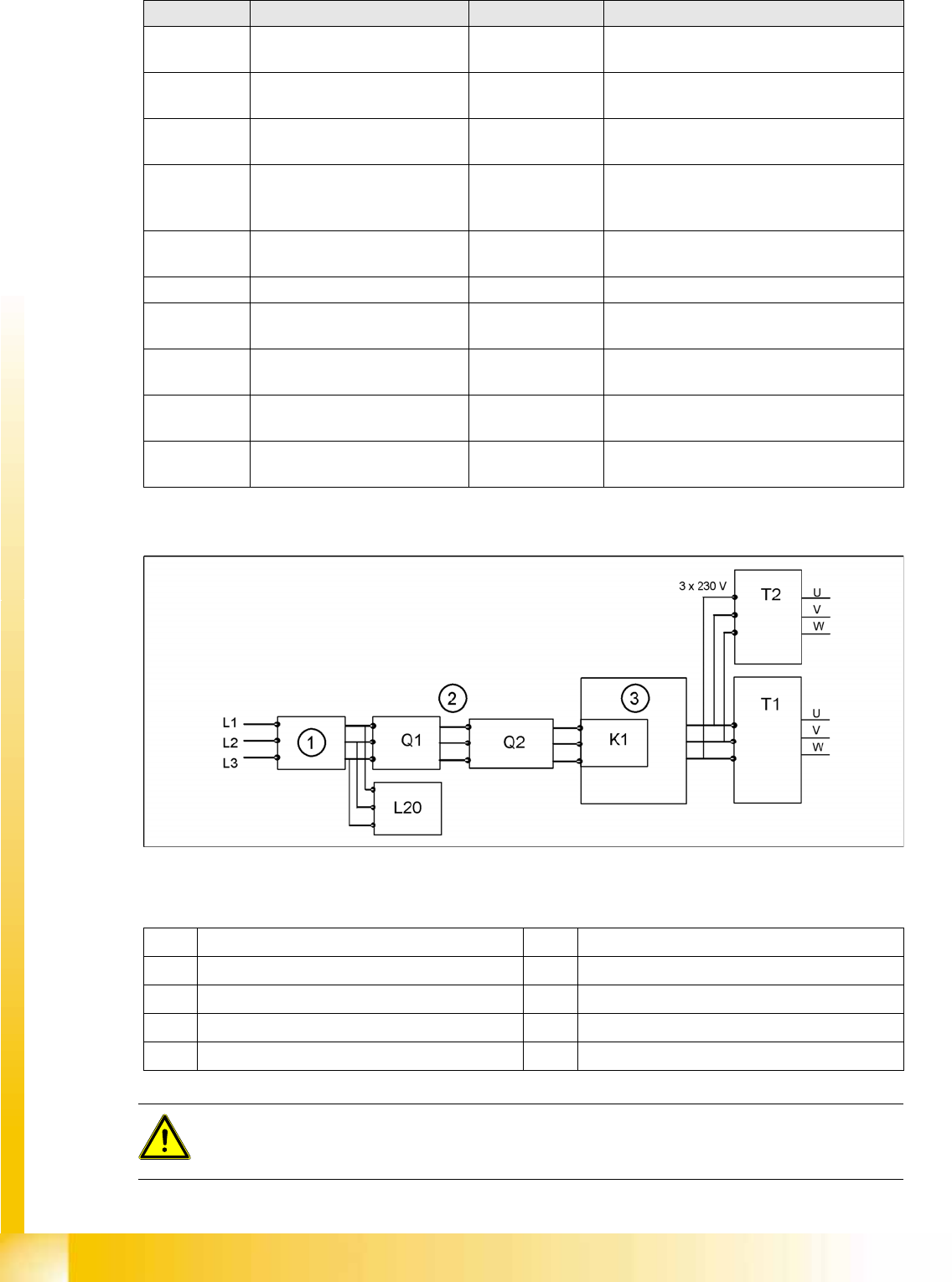
5.2.4.2 Input Voltage
5-6: Input voltage
Legend
F11 Fuse (1A) inrush current
limitation board 1-phase
1, 2 33,6 VDC to GND
F12 Fuse (6 A)
illumination; 1-phase
1, 2 52 VDC to GND
F13 fuse (3A) monitor;
1-phase
1, 2 26 VDC to GND
F14 Fuse (6 A)
cooling device Y motor
1-phase
1, 2 24 VDC to GND
F21 / F22 /
F23
Micro fuse (T6,3A) discharge
inductor L20
1, 2 3 x 204 VAC / 3 x 380 VAC
3 x 400 VAC / 3 x 415 VAC
F61 / F62 fuse (10A) rectifier U4 1, 2 3 x 28 VAC
F81 / F82 Microfuse (T10A)
rectifier U5
1, 2 3 x 23.8 VAC
F111 / F112 Microfuse (T1A)
rectifier U8
1, 2 3x 25.7 (23.8V) VAC
F131 / F132 Microfuse (T4A)
rectifier U10
1, 2 3x 20.5 (19.7V) VAC
F141 / F142 Microfuse (T6,3A)
rectifier U11
1, 2 3x 18.9 (18.7V) VAC
Assembly Designation Contact Voltages
1 Current filter K1 main contactor and inrush current limiter for T1
2 3 phases T1 transformer 1
3 Inrush current limitation board for T1 T2 Transformer 2
Q1 Main switch L20 Discharge inductor
Q2 Motor Circuit Breaker
ATTENTION:
After transformers T1 and T2, the main power potential ends and the machine is only fed by
secondary voltages.