00196044-05 - sg x und x4i fse_en.pdf - 第143页
Communication and Control One Wire Bus - Structure One Wire Bus S tudent Guide (FSE) SIPL ACE X Series and X4I Edition 01/2009 EN Communication and Control 143 4.5.1.4 One Wire Bus Component s Assemblies: 1. Interface 1-…
Communication and Control
One Wire Bus One Wire Bus - Structure
Student Guide (FSE) SIPLACE X Series and X4I
Communication and Control Edition 01/2009 EN
142
4.5.1.3 Function Description
When the machine is switched on, each one wire bus is assigned a fixed CAN ID.
One wire in PA1 --> CAN ID:
07d0
One wire in PA2 --> CAN ID:
07c0
During initialization of the bus system, each station registers with the master, after which the bus is ready
for operation.
In the non operative mode, the voltage level is 5 V on the one wire bus.
A repeat initialization can be performed with the CACCIA tool (see Function Control and Troubleshooting
for Service Work).
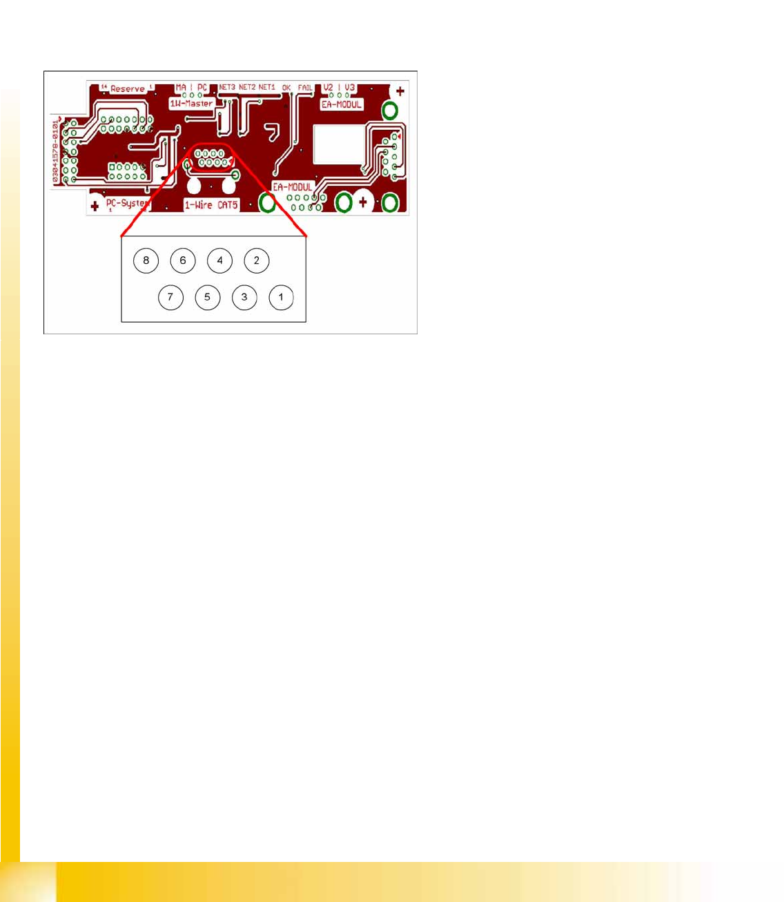
4-44: Interface 1-Wire CAT5
Legend
1. NC row 1 gantry 1/3
2. NC row 2 gantry 1/3
3. Temperature sensors gantry 1
4. Temperature sensors gantry 4
5. NC row 1 gantry 2/4
6. NC row 2 gantry 2/4
7. 24 V
8. GND
For initial analysis, the 5 V level can be measured
at the 1-Wire-CAT5 connector of the interface.
The 24 V at pin 8 can be measured at the old 1-
Wire and serves as voltage supply for the nozzle
changers. The 24 V are fed into the 1-Wire
distributor. However, this is not used at the
interface.
Communication and Control
One Wire Bus - Structure One Wire Bus
Student Guide (FSE) SIPLACE X Series and X4I
Edition 01/2009 EN Communication and Control
143
4.5.1.4 One Wire Bus Components
Assemblies:
1. Interface 1-Wire CAT5 on the SUB/MAIN module
2. 1 wire CAT 5 Gantry on the trailing interface (board between CAN bus and trailing interface)
3. 1 set of temperature sensors (replacement only as a set, due to serial number)
4. EEPROM for gantry recognition
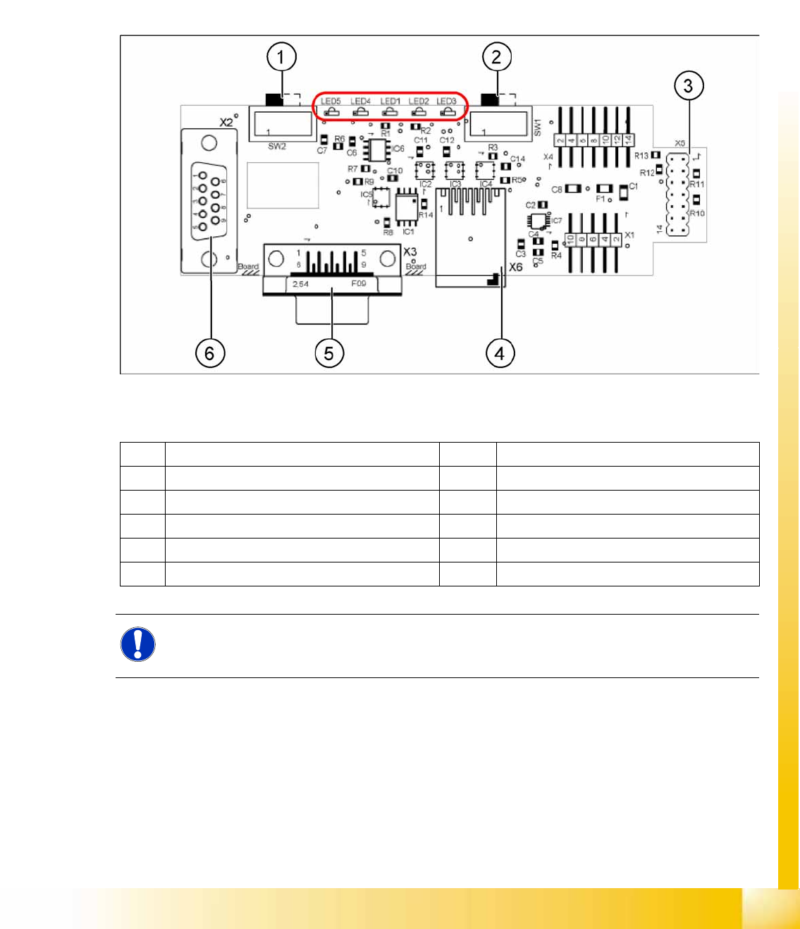
Interface 1-Wire CAT5
4-45: Interface 1-Wire CAT5 on the SUB/MAIN module (version 02) [03041578-01]
Legend:
See also:
J
4.3.10.1 DIP Switch on Main and Subdistributor (for Version -03) [
J
122]
1 MA / PC switch must be set to MA (machine) LED 1 NC 1/3
2 Switch must be set to V2 LED 2 Temperature sensors
3 Interface 1-Wire CAT5 LED 3 NC 4/2
4 Connector CAT5 cable LED 4 Green "OK"
5 CAN Bus interface to the machine LED 5 Green "Error"
6 CAN Bus Interface to I/O module
NOTE:
In version 03, this board is integrated into the I/O module and settings are made with the DIL
switch of the I/O module.
Communication and Control
One Wire Bus One Wire Bus - Structure
Student Guide (FSE) SIPLACE X Series and X4I
Communication and Control Edition 01/2009 EN
144
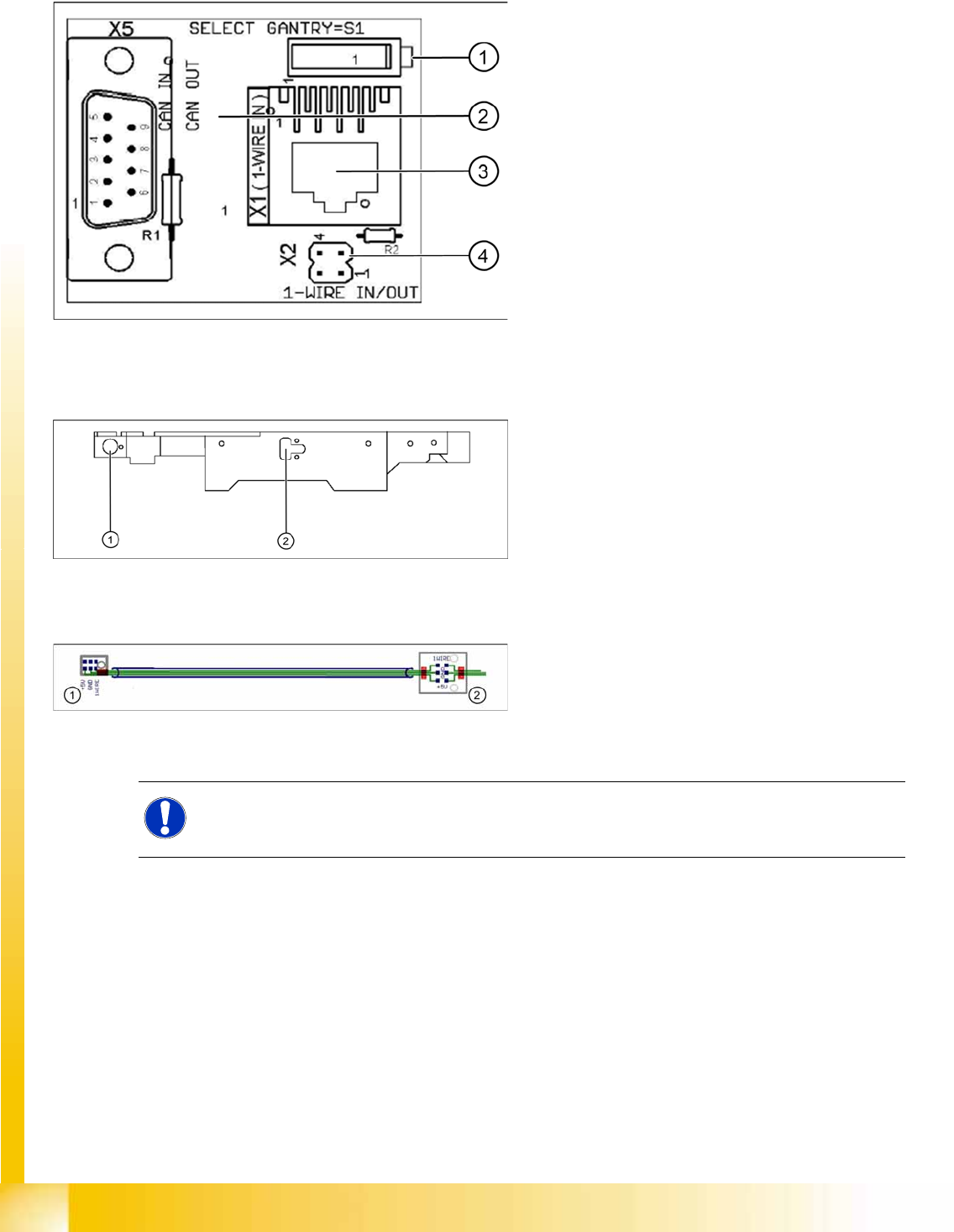
One Wire CAT5 Gantry Board
Temperature Sensors and Gantry Recognition (EEPROM)
4-46: One wire gantry board [03042214-01]
1 wire CAT 5 Gantry on the trailing interface
(board between CAN bus and trailing interface)
Legend:
1. Switches:
Position down = gantry 1/2,
position up = gantry 3/4
2. This board is located directly on the CAN bus
connector of the trailing interface.
3. Connector CAT5 cable direct from the 1 wire
CAT5 interface
4. Connection to the second Gantry in the
placement area
4-47: Position of temperature sensors on the head assembly plate (assembly
side of placement head)
1 set of temperature sensors (replacement only as
a set)
Legend
1. Temperature sensor on the PCB camera
2. Temperature sensor/ EEPROM gantry
recognition
4-48: Temperature sensors / gantry recognition
Legend
1. Temperature sensor on the PCB camera
2. Temperature sensor/ EEPROM gantry
recognition
NOTE:
The temperature sensors are directly connected to the connector X20 or X21 on the head
interface C500. Either one of these connectors can be used.