00196044-05 - sg x und x4i fse_en.pdf - 第404页
Component Handling Changeover Table Overview S tudent Guide (FSE) SI PL ACE X Series and X4I Component Ha ndling Edition 01/2009 EN 404 10.1.1.1 Changeover T able (X T able) The changeover table and the d ocking unit for…
Component Handling
Overview Changeover Table
Student Guide (FSE) SIPLACE X Series and X4I
Edition 01/2009 EN Component Handling
403
10 Component Handling
10.1 Changeover Table
10.1.1 Overview
This chapter describes the preparation of components with the changeover tables, the corresponding
docking unit and the pneumatic cutter.
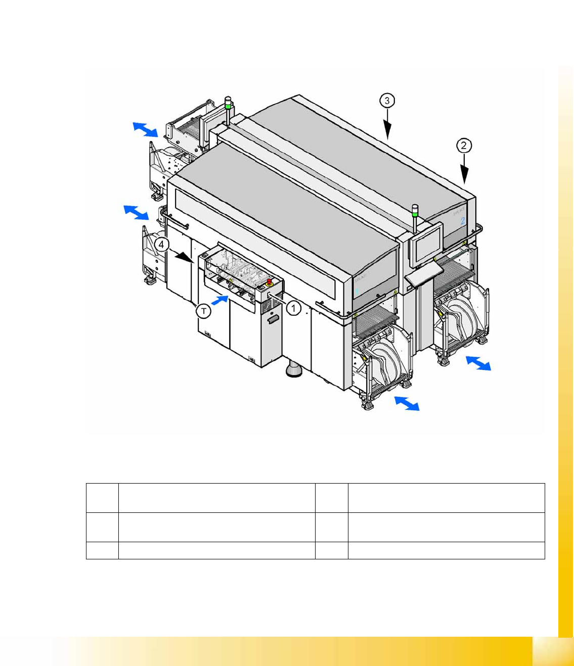
Up to four moveable changeover tables can be docked onto the X machine. The changeover tables are
automatically connected to and disconnected from the docking unit (mechanically and electrically) by
pressing a button. MTC2s can also be used with all X series machines (except X4I).
10-1: Shows the buttons for docking and undocking the COT‘s
Legend
1 Button for docking and undocking the
component trolley to location 1
3 Button for docking and undocking the
component trolley to location 3
2 Button for docking and undocking the
component trolley to location 2
4 Button for docking and undocking the
component trolley to location 4
T Direction of board transport
Component Handling
Changeover Table Overview
Student Guide (FSE) SIPLACE X Series and X4I
Component Handling Edition 01/2009 EN
404
10.1.1.1 Changeover Table (X Table)
The changeover table and the docking unit form a component supply unit.
Technical Data (X Table):
NOTE:
The SIPLACE X4I machine only supports C&P20A heads, X tables and the feeder types 8, 12
and 16 mm.
Feeder capacity 148 tracks width 8mm, 8mm X feeders
74 tracks width 12mm, 12mm X feeders
60 tracks width 16mm, 16mm X feeders tracks width mm.
Feeder locations: 4 changeover tables with integrated waste tape bins
40 locations, each with 8mm X feeders per component trolley at locations 1 and 3
34 locations, each with 8 mm X feeders per component trolley at locations 2 and 4
Feeder types Tape
Interface to the machine Automatic connection to machine during docking (no connection of cables needed)
Power supply
CAN bus connection
Closing the safety loop
Compressed air connection
Changeover table heights: Based on the conveyor height
830 mm ± 15 mm (standard)
900 mm ± 15 mm (SMEMA)
930 mm ± 15 mm (SMEMA)
950 mm ± 15 mm (SMEMA)
Component Handling
Structure of the Changeover Table (X- Table) Changeover Table
Student Guide (FSE) SIPLACE X Series and X4I
Edition 01/2009 EN Component Handling
405
10.1.2 Structure of the Changeover Table (X- Table)
10.1.2.1 Dummy Feeder on the X4I
10.1.3 Changeover Table with One Hand Operation - Function
10.1.3.1 Docking
The docking process can only be performed when the machine is on, compressed air is supplied to the
machine and the safety covers are closed.
To dock the changeover table, push the table as far as possible up to the feed device and press the
button on the machine. On the left and right from the empty tape duct are two centering pins to center
the COT for the final correct pick up position.
The feeder contact plate is raised by two pneumatic cylinders and cam disks while, at the same time, the
entire changeover table is pulled into the machine.
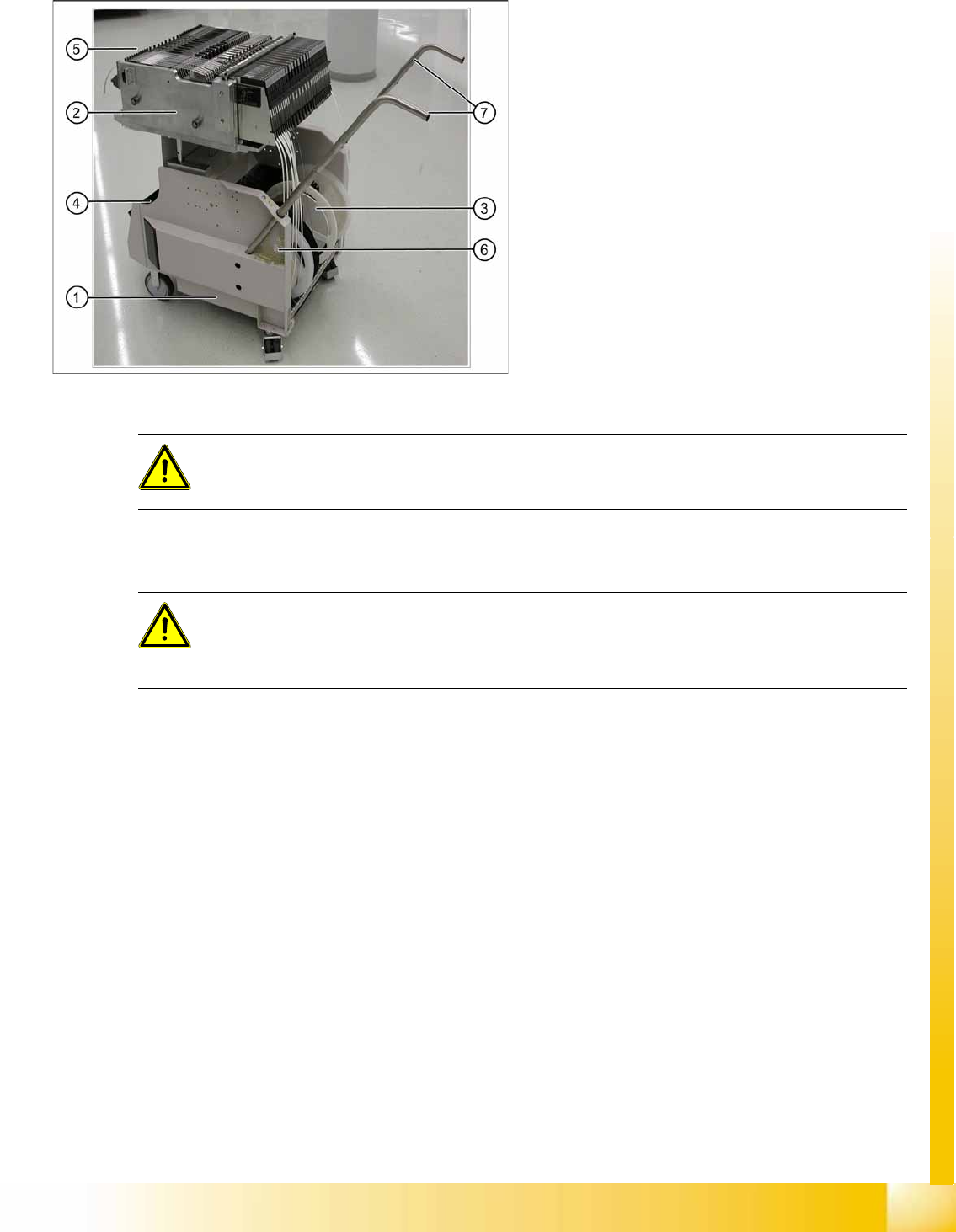
10-2: COT (X- table) - side view
Legend
1. Moveable base
2. Changeover table
3. Tape reels container
4. Tape waste bin
5. Interface power supply, communication,
safety loop
6. Sticker with an ID number as alphanumeric
characters and as a barcode
7. Handles (can be individually swiveled for
model 2)
One pocket can be attached to the side of the
component trolley, for setup list printouts.
CAUTION:
Unused locations are to be fitted with dummy feeders to ensure that unauthorized persons do
not reach into the machine.
ATTENTION:
The 6 inner tracks can not be reached at locations 2 and 4 of the X4I. A dummy feeder is
therefore automatically inserted here. This also contains the position fiducial for calibration of
the tables.