00196044-05 - sg x und x4i fse_en.pdf - 第171页
Energy and Compressed Air Supply Overview S tudent Guide (FSE) SIPL ACE X Series and X4I Edition 01/2009 EN Energy and Compressed Air Supply 171 5 Energy and Compressed Air Supply 5.1 Overview The diagram below shows whe…

Communication and Control
Room for Your Sketches and Notes CAN Commands for Reading and Writing the Board IDs
Student Guide (FSE) SIPLACE X Series and X4I
Communication and Control Edition 01/2009 EN
170
Energy and Compressed Air Supply
Overview
Student Guide (FSE) SIPLACE X Series and X4I
Edition 01/2009 EN Energy and Compressed Air Supply
171
5 Energy and Compressed Air Supply
5.1 Overview
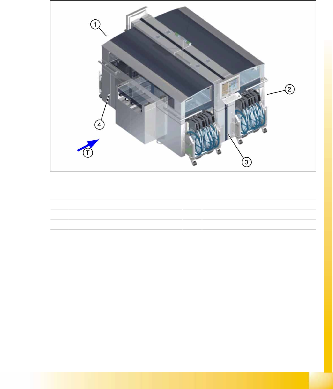
The diagram below shows where the energy supplying and distributing components for system operation
are installed:
5-1: Main components
Legend:
1 Power supply 3 Pneumatic Unit
2 Sector distributor for sector 2 4 Sector distributor for sector 4
T Transport direction
Energy and Compressed Air Supply
Power supply
Student Guide (FSE) SIPLACE X Series and X4I
Energy and Compressed Air Supply Edition 01/2009 EN
172
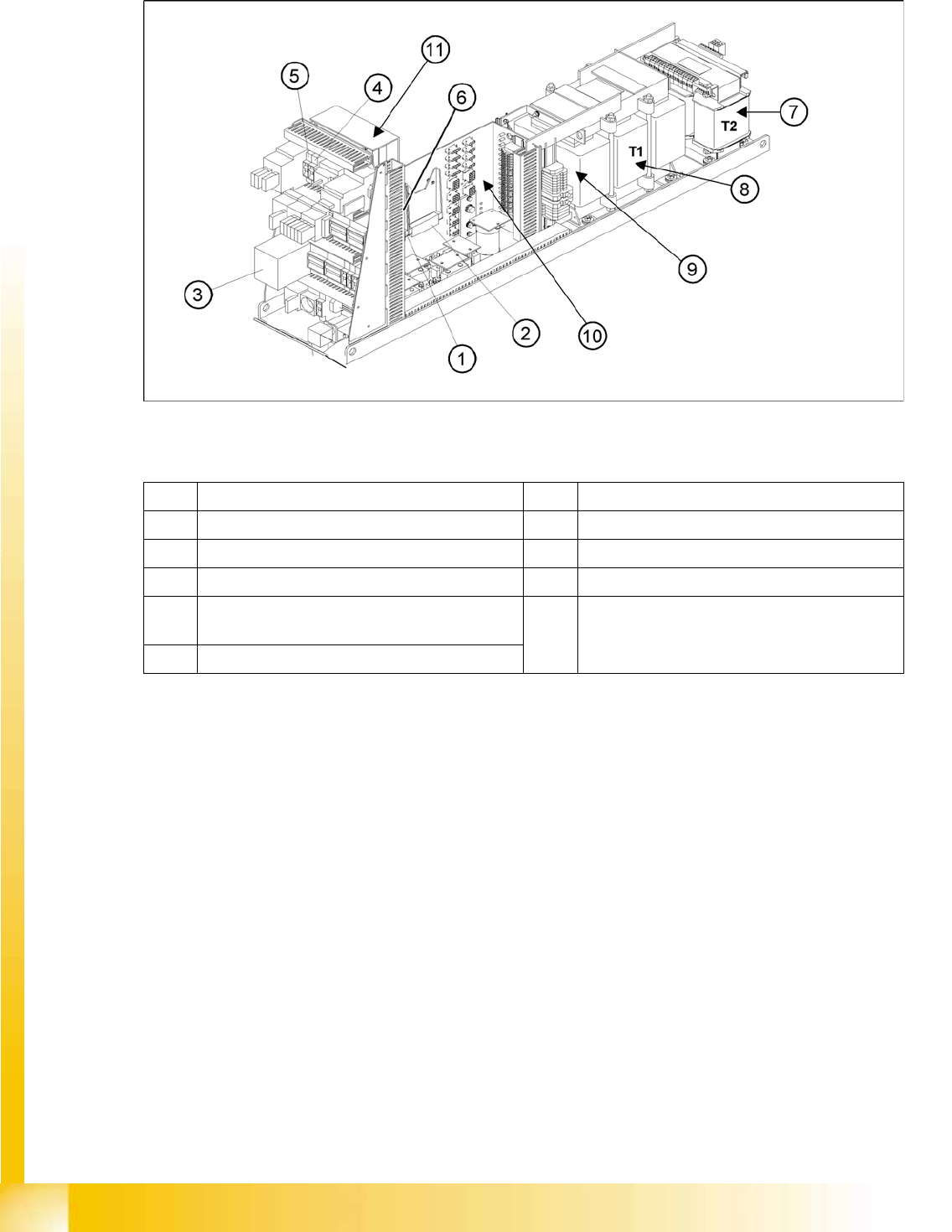
5.2 Power supply
5-2: Main power supply unit
Legend
1 DC/DC Converter 24 V 7 Transformer T2
2 DC/DC Converter 5 V and additional 24V 8 Transformer T1
3 Protective contactor combination K6 (SSK) 9 Fuse F61 – Fuse F142
4 Fuse F5 (10A) for star axis 10 Main distributor voltage supply
5 Fuse F11(1A) for transformer inrush current
limitation board
11 Inrush current limitation board
a: Transformer: EST
b: Servo: Ess
6 Discharge inductor L20