00196044-05 - sg x und x4i fse_en.pdf - 第300页
Collect, Pick and Place Head (CPP) Overview Application S tudent Guide (FSE) SI PL ACE X Series and X4I Collect, Pick and Place Head (CPP) Edition 01/2 009 EN 300 8.2.1 Application The CPP head can be used in the followi…
Collect, Pick and Place Head (CPP)
Important Information
Student Guide (FSE) SIPLACE X Series and X4I
Edition 01/2009 EN Collect, Pick and Place Head (CPP)
299
8 Collect, Pick and Place Head (CPP)
8.1 Important Information
8.2 Overview
ATTENTION: Head exchange
When replacing the Twin Head with a CPP head with MTC2 in this placement area, you need
to fit a bumper extension, to limit the Y travel range. After switching the machine back on, you
then need to redetermine the machine zero point and the travel ranges.
When you use a Twin Head again, you need to remove the bumper extension.
ATTENTION: Risk of head crash!
When installing a CPP head with a stationary camera, this needs to be fitted in the top position,
otherwise there is a risk of a head crash!
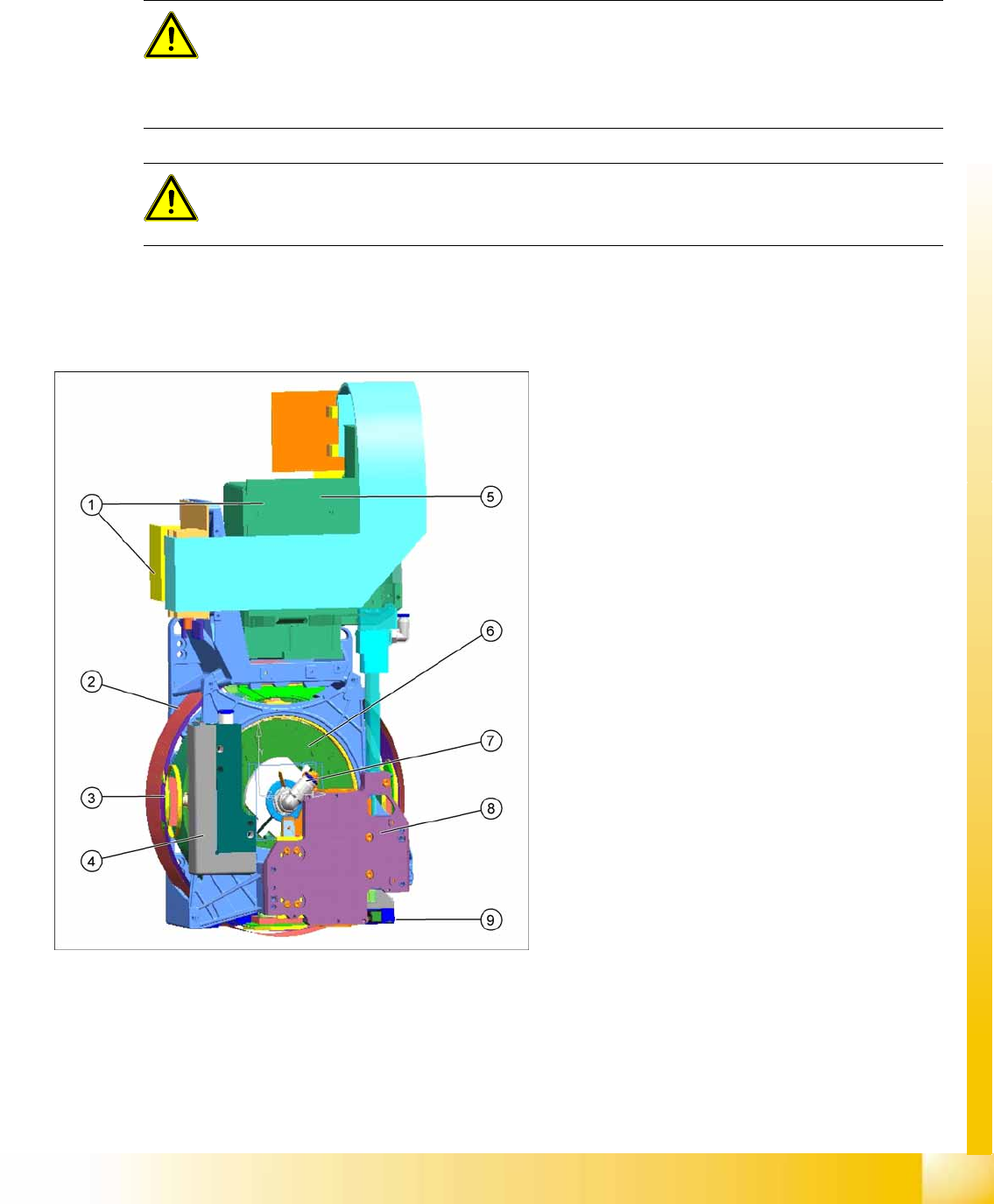
8-1: CPP head overview
CPP head (without component camera)
[03053528-xx]
Legend
1. Intermediate distributor 1 and 2
2. Star motor (integrated in head housing)
3. DP axis (as direct drive)
4. Pressure Control Valve
5. Component camera (standard: SST29)
6. Single Core Solution (SCS) – control DP
drives
7. Hold circuit with venturi nozzles and valve
terminal
8. Z axis with return cylinder
9. Component sensor in the pick and place
position

Collect, Pick and Place Head (CPP)
Overview Application
Student Guide (FSE) SIPLACE X Series and X4I
Collect, Pick and Place Head (CPP) Edition 01/2009 EN
300
8.2.1 Application
The CPP head can be used in the following machines:
X series (X2, X3, X4, X4I)
SX1 - machine with one gantry
SX2 - machine with two gantries
8.2.2 Configuration
The CPP head with 12 segments can be configured as follows:
Low installation height (CPP_L)
High installation height (CPP_H)
8.2.3 Requirements
The following requirements needs to be met for using the CPP head in X series machines:
A364 axis controller with servo amplifier SDS120-1.5Z2 or HCU (Head Control Unit)
Station software ≥ SW702
Box PC
Head plate for CPP head
X tables and X feeders
Addressing the nozzle changer via the CAN node module
Both control concepts are possible for the star and Z axis.

Collect, Pick and Place Head (CPP)
Technical Data Overview
Student Guide (FSE) SIPLACE X Series and X4I
Edition 01/2009 EN Collect, Pick and Place Head (CPP)
301
8.2.4 Technical Data
The component spectrum depends on the component camera fitted and the resulting placement mode.
Component
spectrum
Component
camera
SST28
Component
camera
SST29
Component
camera
SST38
FC camera
SST25
IC Camera
SST33
IC camera
SST36
C&P mode
(min.
component)
0402 0201 01005 01005 (0603) (0603)
C&P mode
(max.
component)
18.7x18.7 mm 27x27 mm /
(µBGA to
18x18 mm)
16x16 mm
P&P mode
(max.
component)
16x16 mm 50x40 mm 32x32 mm
Mixed mode
(max.
component)
16x16 mm 32x32 mm 32x32 mm
Component height (CPP_H) max. 8.5 mm C&P mode
max. 8.5-11.5 mm in P&P and mixed mode
Component height (CPP_L) max. 6 mm, at max. placement performance
Placement accuracy +/- 50 µm (4 sigma) in C&P mode with SST38
+/- 55 µm (4 sigma) in C&P mode with SST29
+/- 60 µm (4 sigma) in C&P mode with SST28
+/- 45 µm (4 sigma) in P&P mode with stationary cameras
Put down contact force 1-3 N ±0.5 N (current sensor)
2.2 N ±0.5 N (light barrier)
3-10 N ±15 % (current sensor)
Weight of head approx. 5.3 kg with component camera
Component weight: max. 4 g in C&P mode, mixed mode
max. 8 g in P&P mode
Component cameras SST28 (min. component 0402 to 18.7x18.7)
SST29 (0201 to 27x27, standard)
SST38 (01005 to 16x16)