00196044-05 - sg x und x4i fse_en.pdf - 第220页
Gantry Settings Anticrash Function for the A364 Axis Card S tudent Guide (FSE) SI PL ACE X Series and X4I Gantry Edition 01/2009 EN 220 6.3.3 Anticrash Function fo r the A364 Axis Card 6.3.3.1 Anticrash Function for the …
Gantry
PCB Boards on the Gantry Settings
Student Guide (FSE) SIPLACE X Series and X4I
Edition 01/2009 EN Gantry
219
6.3.2.4 Check the DIP Switches
DIP Switches on the Head Interface
* Not all gantries may be available, depending on the machine type.
DIP Switch on the Vision Board (Digital Version 02)
* Not all gantries may be available, depending on the machine type.
S Gantry* Comments
1 2 3 4
1 OFF ON OFF ON P0 - Gantry address switch 1
2OFF OFF ON ONP1 - Gantry address switch 2
3ONONONONCAN R - CAN terminator (always OFF for Twin
Head)
4 OFF OFF OFF OFF Boot - CAN processor 16 bit
5 OFF OFF OFF OFF Reset - CAN processor 16 bit
6 OFF OFF OFF OFF C0 - CAN Address switch
7 OFF OFF OFF OFF C1 - CAN Address switch
8 OFF OFF OFF OFF WPE - Write protect enable at the moment
OFF
ATTENTION:
Switch 3 (does not apply for X4I machines)
With Head Modularity pay attention: That terminating CAN resistor is set correctly. This means,
Switch 3 is set to ON for C&P and to OFF for Twin Head.
S Gantry* Comments
1 2 3 4
1 OFF OFF OFF OFF Reset - CAN processor
2 OFF ON OFF ON PID0 address switch 1 -> gantry
3OFF OFF ON ONPID1 address switch 2 -> gantry
4 OFF OFF OFF OFF CAN R - switch for the terminal resistor on the
CAN bus
5ONONONONSpeed: ON = 1 Mbit/s, OFF = 500 Kbit/s
6ONONONONCAN ID - for X machine ON

Gantry
Settings Anticrash Function for the A364 Axis Card
Student Guide (FSE) SIPLACE X Series and X4I
Gantry Edition 01/2009 EN
220
6.3.3 Anticrash Function for the A364 Axis Card
6.3.3.1 Anticrash Function for the A364
The anticrash function is no longer provided by the anticrash board but instead by the A364 software
(application 1). This means that the proximity switches used to monitor the travel range and the
sensor for monitoring the gantry spacing are no longer required.
Tasks:
– Monitoring the X and Y axis travel ranges
Evaluation of the actual position of the respective axis in the direction of the bumper, based on
the speed.
– Monitoring the distance of both Y axes in a placement area
Evaluation of the actual position of the own gantry and the partner gantry at gantry crash
monitoring.
– Count error monitoring of the gantry axis
Monitoring incoming count pulses (edge control) over time.
6.3.3.2 Anticrash Monitoring for the A364
The anticrash function is activated after the X/Y axes have been referenced. When the gantry axes are
referenced for the first time, anticrash monitoring is not active, which does not matter, due to the low
reference speed.
After this, the bit is set for the anticrash monitoring function and the actual position for the relevant
partner gantry is continuously communicated via the SPI Bus.
The following information is exchanged between the Y axes:
Actual position and speed of its own gantry
Status information (reference state, anticrash monitoring state ).
6.3.3.3 Error "Gantry Crash"
A “gantry crash” error is established by calculating the position difference and speed difference for both
axes. A gantry crash error is signaled via the axis card and the CAN Bus. The servo is released for both
axes and both need to be referenced again.
6.3.3.4 Count Error:
If the axis board detects a "fatal count error", the axis concerned will be released and the anticrash
function disabled. The other axis is informed of this in the status information and will also disable the
anticrash function. The released axis now needs to be referenced again,
after which the anticrash function will be re-enabled for both axes.
Gantry
Mechanical Adjustment of the Incremental Encoder Settings
Student Guide (FSE) SIPLACE X Series and X4I
Edition 01/2009 EN Gantry
221
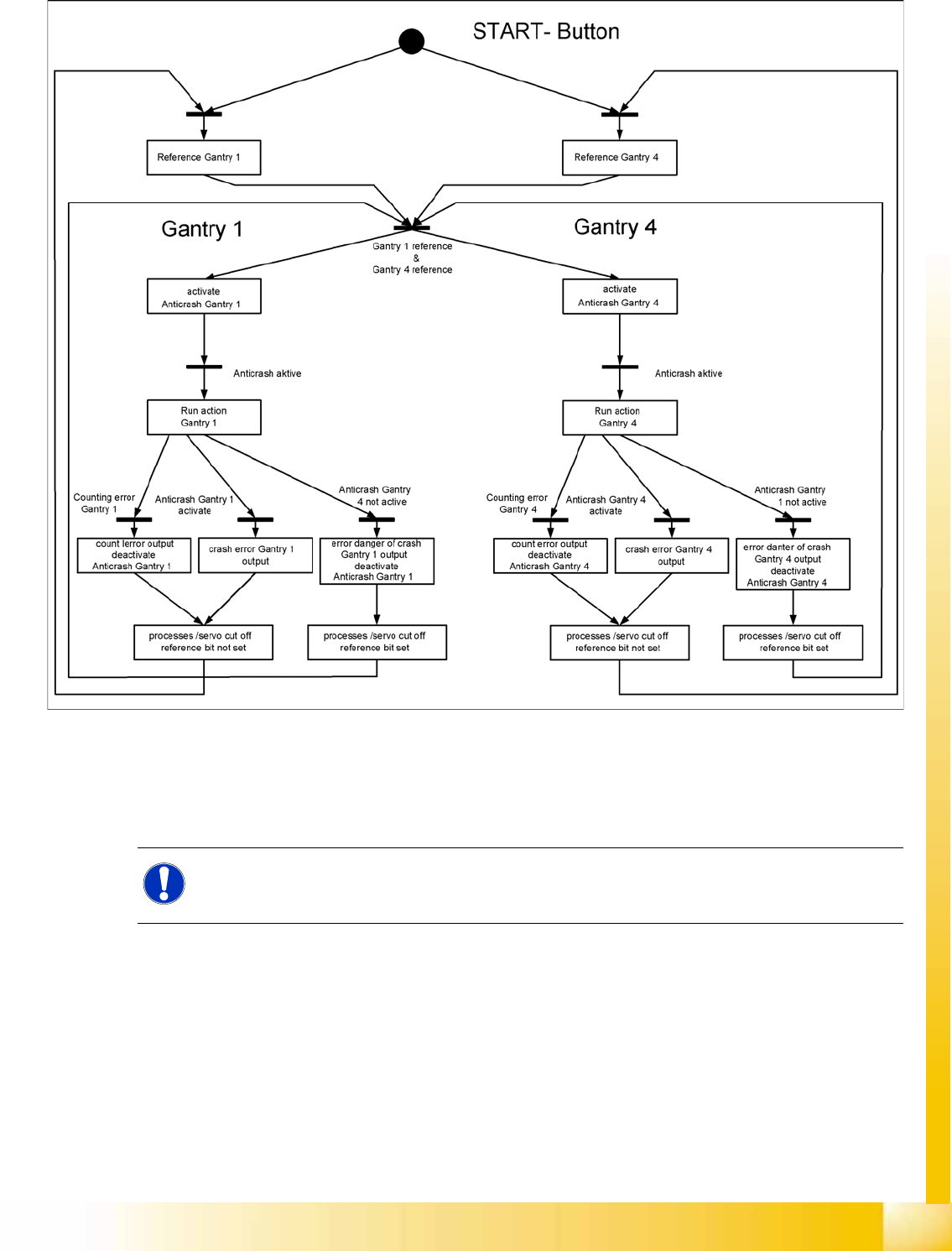
6.3.3.5 Anticrash Function
6-11: Example of the anticrash function sequence in placement area 1
6.3.4 Mechanical Adjustment of the Incremental Encoder
The incremental encoders (read units) on the X and Y axis are adjusted mechanically to a distance of
0.4 mm +/- 0.1 mm to the incremental scale.
After this adjustment of the incremental encoder you have to check the zero pulse and track signals.
NOTE:
To set this distance, use one or more feeler gauges (small plastic disks) with a total thickness
of 0.4 mm.