00196044-05 - sg x und x4i fse_en.pdf - 第499页
Calibration Zero Point Correction for Z and Star Axes Additional Functions S tudent Guide (FSE) SIPL ACE X Series and X4I Edition 01/2009 EN Calibration 503 12.6.3.1 Function Description: The Z axis moves up in current…
Calibration
Additional Functions Zero Point Correction for Z and Star Axes
Student Guide (FSE) SIPLACE X Series and X4I
Calibration Edition 01/2009 EN
502
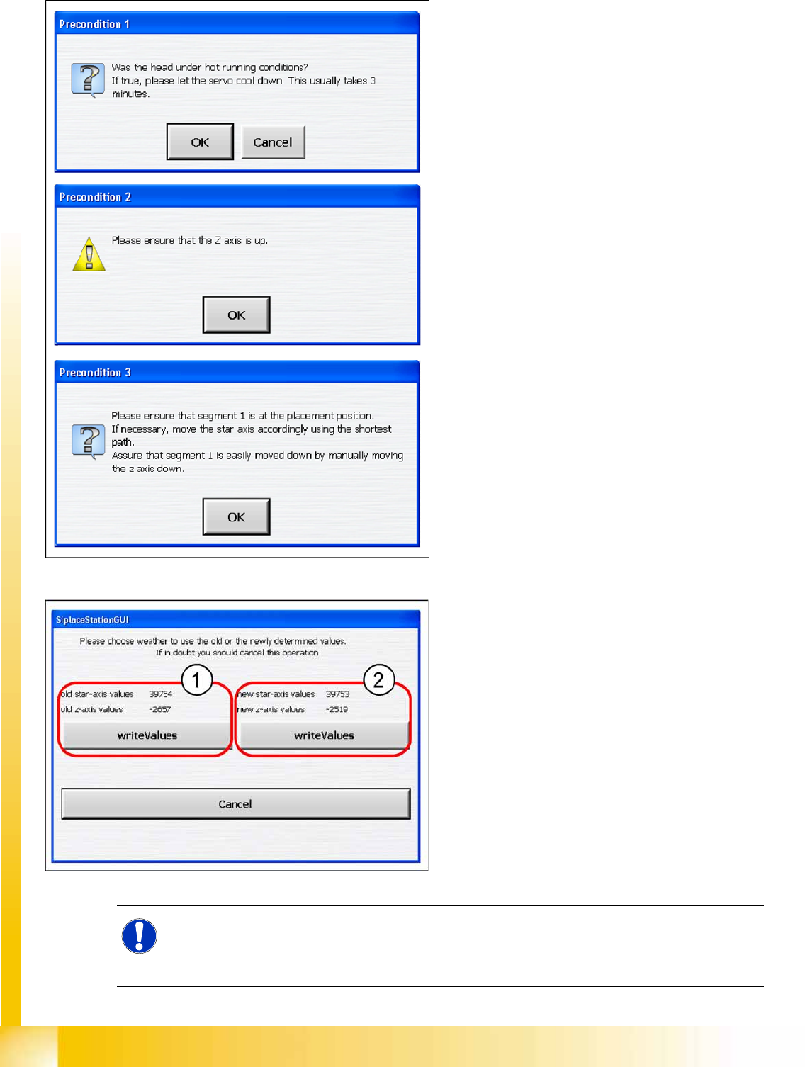
X Check whether the following conditions are
fulfilled and confirm the messages shown:
Check whether the servo has cooled down.
Check the position of the Z axis.
Rotate the star with segment 1 by the shortest
route, into the placement position.
X Close the machine cover.
X Press the
Start button
on the machine.
X Select
OK
on the monitor.
Result
X You can now save the old (1) or new (2)
values.
These values will be saved in the head
EPROM and in the XML file.
NOTE:
If the calibration run was not successful, please check the travel range of the Z axis. The max.
and min. travel of the Z axis (C&P20A) is 34000 digits and -400 digits. The data can be found at
C:\Sirio\Type\Subsystems\PlaceHead.VHS.A364.xml
.

Calibration
Zero Point Correction for Z and Star Axes Additional Functions
Student Guide (FSE) SIPLACE X Series and X4I
Edition 01/2009 EN Calibration
503
12.6.3.1 Function Description:
The Z axis moves up in current sensor mode and sets the position counter to 0.
Then the Z- axis moves down to 18000 digits until the ball bearing of the Z axis is between the
raceway of the star axis.
The star turns left and right and calculated the average value. This is the new zero point correction
(zpc) value of the star axis.
The Z axis moves further down until the ball bearing (segment) is level with the center of the raceway
gap (star).
The star turns right into the gap of the raceway and the Z axis uses the jaws to push the ball bearing
against the raceway. The Z axis position is read.
Now the Z axis position is read out from the left side of the raceway gap, using the same procedure
as that for the right side.
The new zero point correction will now be calculated for the Z axis:
Z position - diameter of ball bearing = thickness of raceway = new ZPC Z axis.
NOTE:
If the function to determine the Z and star axis zero point correction is unsuccessful, use a
setting gauge to adjust the Z axis jaws.
This work may only be performed by Siemens service technicians.
NOTE:
The data is saved in the file for the relevant head, e.g. at
C:\Sirio\Work\Individual\Gantry_1_R.VHS.Indiv.xml
for gantry 1 and is also written to the
head EPROM at the same time.
Calibration
Additional Functions Configuring the Conveyor
Student Guide (FSE) SIPLACE X Series and X4I
Calibration Edition 01/2009 EN
504
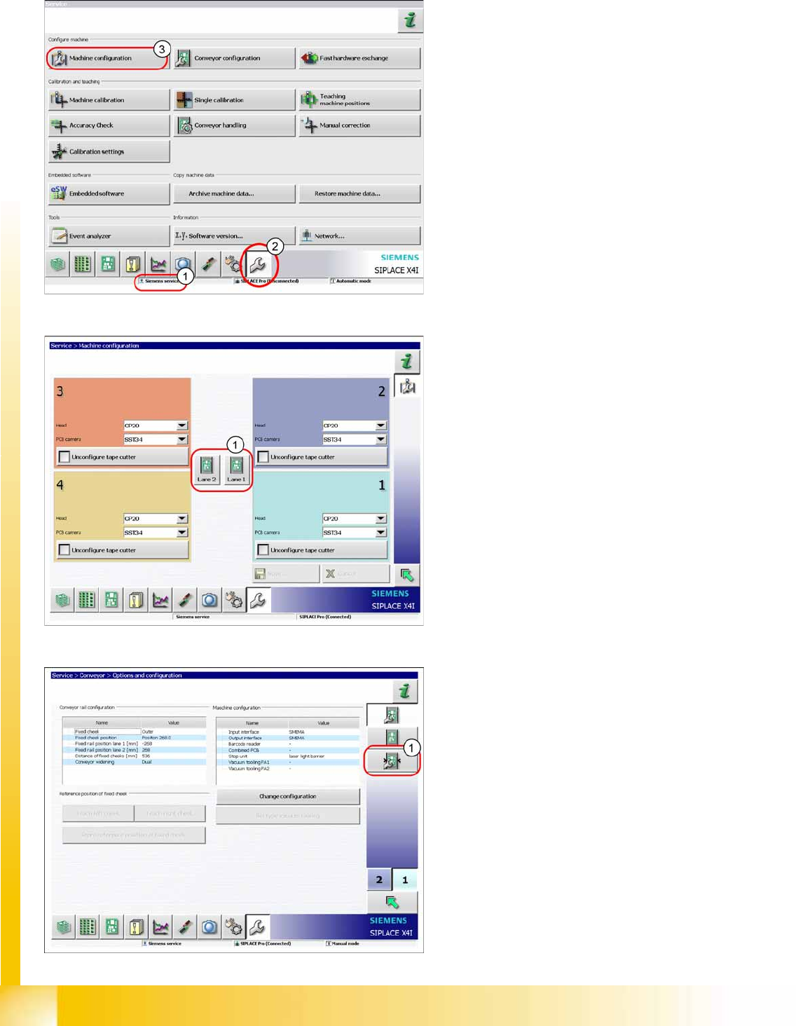
12.6.4 Configuring the Conveyor
This function can be performed with the user level
(1)
Siemens service
.
X Switch over to the menu
Service.
(2).
X Select
Machine configuration
(3).
X Select the lane (1).
X Select
Configuring the Conveyor
(1).