00196044-05 - sg x und x4i fse_en.pdf - 第335页
Collect, Pick and Place Head (CPP) Standard Mode - Placement: Z Axis Up Pickup and Placement Cycle for CPP S tudent Guide (FSE) SIPL ACE X Series and X4I Edition 01/2009 EN Collect, Pick and Place Head (CPP) 335 8.4.14 S…
Collect, Pick and Place Head (CPP)
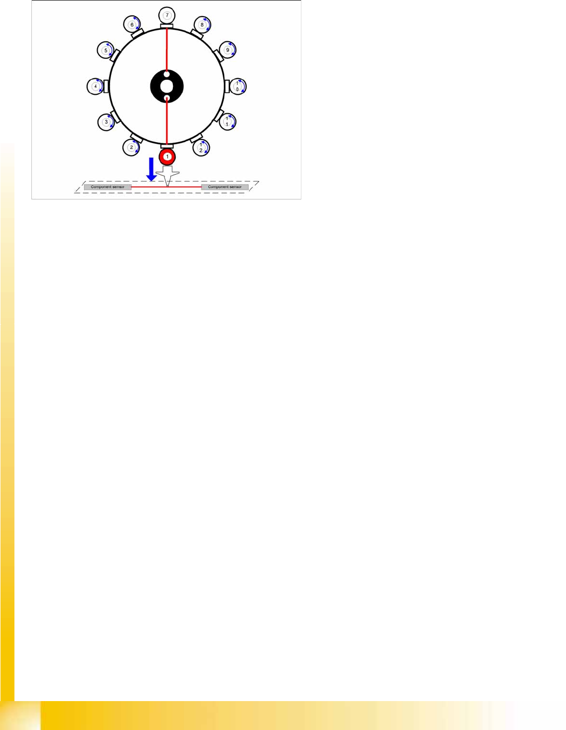
Pickup and Placement Cycle for CPP Standard Mode - Placement: Z Axis Down
Student Guide (FSE) SIPLACE X Series and X4I
Collect, Pick and Place Head (CPP) Edition 01/2009 EN
334
8.4.13 Standard Mode - Placement: Z Axis Down
Axis controller:
Enable signal for "light barrier down" function
LB down switches:
End signal Z axis positioning downwards;
Digital pressure control valve: switches "Air blast ON"
Pickup/placement position; air blast threshold "place component"reached? YES
8-14: Detailed component placement procedure: Z Axis Down
In this mode (light barrier down) the placement
force at the placement head is around 2N.
End position signal for X and Y axes--> Z axis
starts:
Positioning of Z axis downwards
Component sensor checks nozzle length with
component. Z axis measurement value -
nozzle length "with component" - threshold
reached? YES
End position signal for star axis:
Performs vacuum test "before placement".
"Vacuum closed" threshold reached? YES to
determine whether the component is held by
holding force on the nozzle.
Collect, Pick and Place Head (CPP)
Standard Mode - Placement: Z Axis Up Pickup and Placement Cycle for CPP
Student Guide (FSE) SIPLACE X Series and X4I
Edition 01/2009 EN Collect, Pick and Place Head (CPP)
335
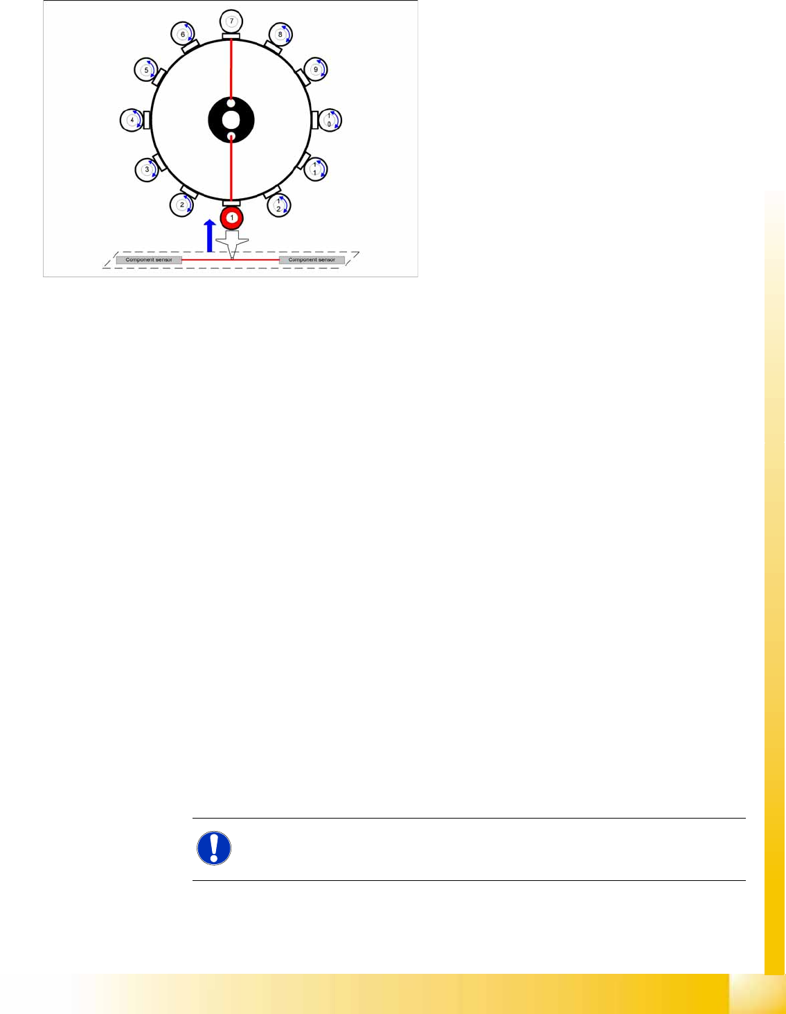
8.4.14 Standard Mode - Placement: Z Axis Up
8.4.15 Optical Nozzle Query
After the reference run, the gantries move into the wait position and performs the first nozzle
scanning. During the production, a nozzle scanning run is performed after 350 head cycles (can be
set by Siemens service if required) and after the completion of the board currently processed. This
ensures that the nozzle quality is continually checked during the production process:
– All nozzles listed in the scan parameters of the station database will be measured by the
component camera.
– If there is any deviation from the defined size, shape or brightness, the machine will show the
message:
Nozzle worn down or contaminated
.
Tiny nozzles may touch the solder paste or the glue because of component shift and the minimum
component height.
The number of components per segment (number of head cycles), after the next nozzle query has
been performed, should be adjusted to the customer's process requirements. This check is always
performed after completing PCB processing.
8-15: Detailed component placement procedure: Z Axis Up
LB down switches:
...
Pickup/placement position; air blast threshold
"place component"reached? YES
Start signal for upwards movement
Z axis starts:
Z axis positioning upwards
Head firmware:
Digital pressure control valve: switches air
blast OFF
Reset "light barrier down" signal
Axis controller:
Z axis measurement value for nozzle "empty"
and
Z axis in safe area =
Enable X, Y gantry axes.
Vacuum query:
Vacuum threshold for holding circuit reached?
YES
Star axis starts.
NOTE:
The nozzle quality check can be configured in four different levels, via the station
interface.
Collect, Pick and Place Head (CPP)
Settings Board Descriptions
Student Guide (FSE) SIPLACE X Series and X4I
Collect, Pick and Place Head (CPP) Edition 01/2009 EN
336
8.5 Settings
8.5.1 Board Descriptions
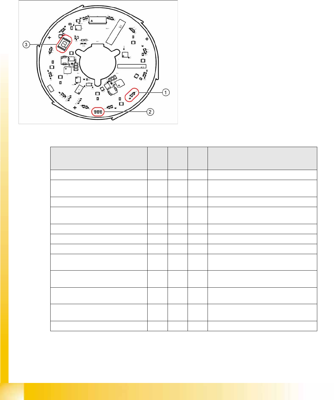
8.5.1.1 Power Module
The 7 segment display (3) provides information about the processor status.
Legend
1. Two LEDs for the status of each DP drive
2. Three LEDs for the operating voltages
3. 7 segment display for the processor status
The status of each DP drive is shown by two LEDs
(green, red) (1).
Three other LEDs (2) show the operating voltages:
Inlet voltage P24 – 24 V
Internal voltage DC/DC converter Vcc – 2.5 V
Internal voltage DC/DC converter Vcc3 – 2.5 V
Status LED
red
LED
green
7
segm
ent
Comment
De energized Off Off 8 LEDs and 7 segment off
Download ZDS (Z down sensor / Z
bottom sensor)
Flash
es
Flash
es
LEDs flash alternatively with high frequency
Download SCS 8 Visualization on 7 segment display
Wait for baud rate recognition
(baud rate not yet recognized)
8 Visualization on 7 segment display
Baud rate recognition error 8 Visualization on 7 segment display
CAN error (error frames) 8 Visualization on 7 segment display
SCS application missing (BIOS active) 8 Visualization on 7 segment display
ZDS application missing (BIOS active) Flash
es
Off Red LED flashes
Error in application 2
e.g. leff error
Off Off Red LED shines permanently
Z down sensor not initialized Flash
es
Off Red LED flashes
DP is referenced but encoder error line
is set
Flash
es
On Red LED flashes / Green LED shines
Z down sensor - no communication Off Off LEDs off