00196044-05 - sg x und x4i fse_en.pdf - 第150页
Communication and Control One Wire Bus Function Control and Troubleshooting for Service Work S tudent Guide (FSE) SI PL ACE X Series and X4I Communication and Control Edition 01/2009 EN 150 4.5.2.2 Function Control with …

Communication and Control
Function Control and Troubleshooting for Service Work One Wire Bus
Student Guide (FSE) SIPLACE X Series and X4I
Edition 01/2009 EN Communication and Control
149
Assignment X4I and X Series (from SW 70x) PA1
Subsystem Hardware components Comments
NC, 1, coupler, 00 1-Wire CAT5 interface on
the I/O module
Not needed, as the NC operates with CAN
nodes.
Temperature, 20, coupler, 00 1-Wire CAT5 interface on
the I/O module
NC, 4, coupler, 00 1-Wire CAT5 interface on
the I/O module
Not needed, as the NC operates with CAN
nodes.
Mainpath, 0, IO_2C, 01
Mainpath, 0, E2_512B, 01
1-Wire CAT5 interface on
the I/O module
1-Wire-CAT5 board interface will be
integrated later into the I/O module version
03
Temperature, 1, IO_2C,01
Temperature, 20, IO_2C,81
1-Wire CAT5 interface on
the I/O module
Temperature, 20, E2_32B, 01
temperature, 20, E2_512B, 61
Temperature, 20, temperature, 10
Temperature, 20, temperature, 11
Temperature, 1, IO_2C,01
Temperature sensors
Gantry 4
The two temperature sensors form a unit and
can only be replaced as a set. The gantry
recognition part can not be replaced.
Temperature, 20, E2_32B, 81
Temperature, 20, E2_512B, e1
Temperature, 20, temperature, 90
Temperature, 20, temperature, 91
Temperature, 20, IO_2C,81
Temperature sensors
Gantry 1
The two temperature sensors form a unit and
can only be replaced as a set. The gantry
recognition part can not be replaced.
Communication and Control
One Wire Bus Function Control and Troubleshooting for Service Work
Student Guide (FSE) SIPLACE X Series and X4I
Communication and Control Edition 01/2009 EN
150
4.5.2.2 Function Control with Caccia
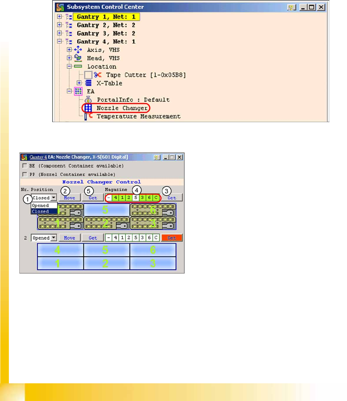
Example - nozzle changer (NC)
In addition to the station software, there are also two other means for checking the function of the NC.
NC menu
X Open the
IO
folder for the relevant location in the
Subsystem control center
.
X Double-click on
Nozzle Changer
4-51: Subsystem control center (nozzle changer)
X the following menu will appear:
4-52: I/O nozzle changer
Legend
1. Selection window, open/close NC row 1
2. Performs the selected function
3. Status query magazine (micro switch under
the magazine)
4. Status display magazine
5. Status display NC opened / closed
Communication and Control
Function Control and Troubleshooting for Service Work One Wire Bus
Student Guide (FSE) SIPLACE X Series and X4I
Edition 01/2009 EN Communication and Control
151
Function Control with CAN Bus Commands
Open and close the nozzle changer
Z Preparation: see subsystem queries.
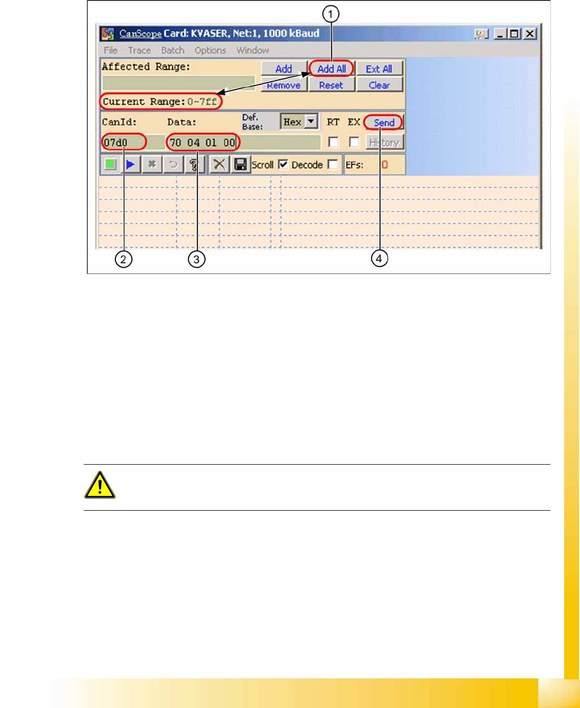
X Open the network window.
4-53: CAN scope NET 1 1 MBaud (network window)
X (1) Select the address range
Add All
. At
Current Range
you will see
0-7ff
.
X (2) Enter the CAN ID for the relevant CAN bus path.
Placement area 1:
07d0
Placement area 2:
07c0
X (3) Enter the command
70 04 01 00
with spaces
70
--> Move command
04
--> Gantry 4
01
--> NC row 1
00
--> (open NC) /
01
--> closed (close NC)
X (4) Select
Send
.
The relevant NC should now open or close, as required.
ATTENTION:
Direct CAN bus commands should only be used by specially trained and qualified service
technicians.