00196044-05 - sg x und x4i fse_en.pdf - 第144页
Communication and Control One Wire Bus One Wire Bus - Structure S tudent Guide (FSE) SI PL ACE X Series and X4I Communication and Control Edition 01/2009 EN 144 One Wire CA T5 Gantry Board T emperature Sensors and G antr…
Communication and Control
One Wire Bus - Structure One Wire Bus
Student Guide (FSE) SIPLACE X Series and X4I
Edition 01/2009 EN Communication and Control
143
4.5.1.4 One Wire Bus Components
Assemblies:
1. Interface 1-Wire CAT5 on the SUB/MAIN module
2. 1 wire CAT 5 Gantry on the trailing interface (board between CAN bus and trailing interface)
3. 1 set of temperature sensors (replacement only as a set, due to serial number)
4. EEPROM for gantry recognition
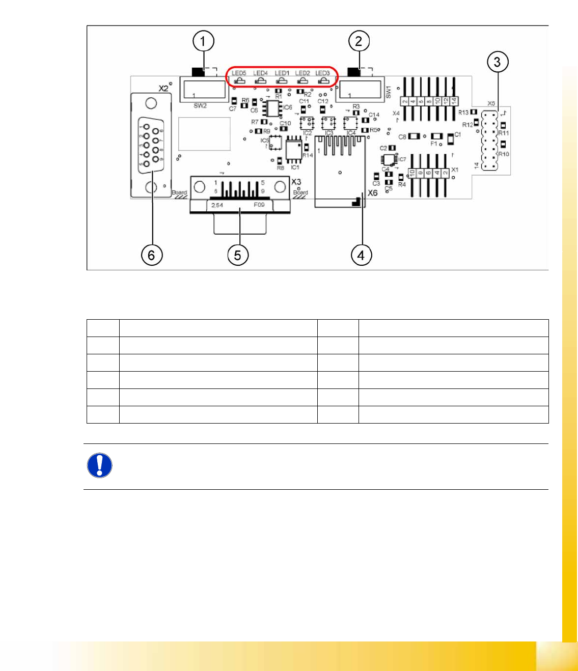
Interface 1-Wire CAT5
4-45: Interface 1-Wire CAT5 on the SUB/MAIN module (version 02) [03041578-01]
Legend:
See also:
J
4.3.10.1 DIP Switch on Main and Subdistributor (for Version -03) [
J
122]
1 MA / PC switch must be set to MA (machine) LED 1 NC 1/3
2 Switch must be set to V2 LED 2 Temperature sensors
3 Interface 1-Wire CAT5 LED 3 NC 4/2
4 Connector CAT5 cable LED 4 Green "OK"
5 CAN Bus interface to the machine LED 5 Green "Error"
6 CAN Bus Interface to I/O module
NOTE:
In version 03, this board is integrated into the I/O module and settings are made with the DIL
switch of the I/O module.
Communication and Control
One Wire Bus One Wire Bus - Structure
Student Guide (FSE) SIPLACE X Series and X4I
Communication and Control Edition 01/2009 EN
144
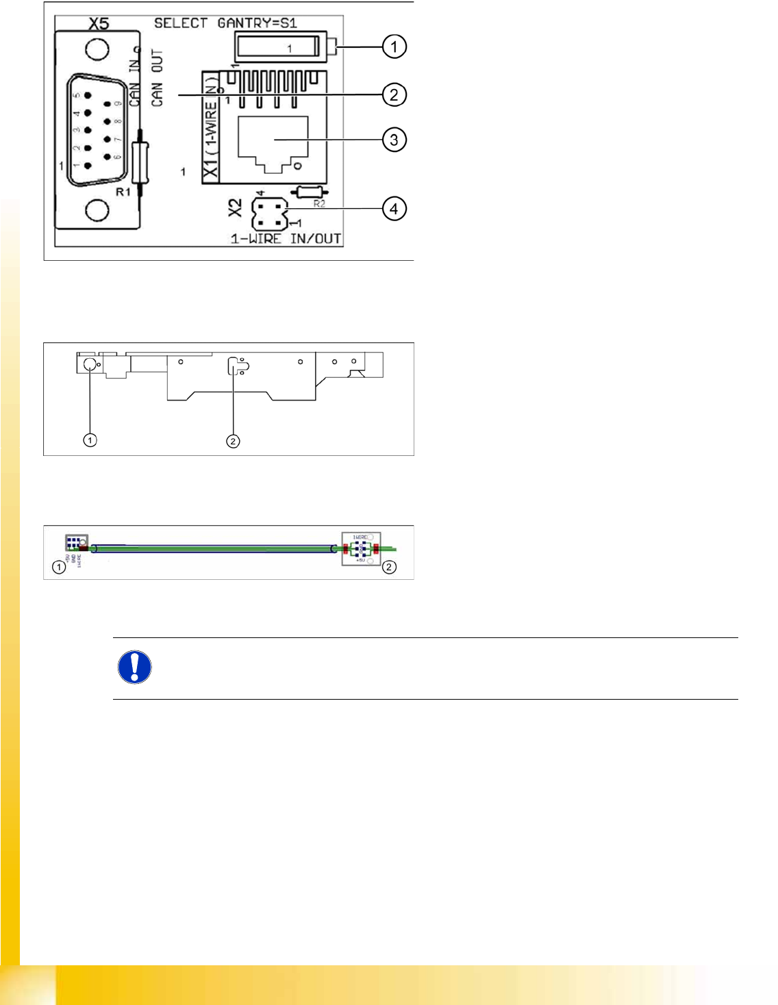
One Wire CAT5 Gantry Board
Temperature Sensors and Gantry Recognition (EEPROM)
4-46: One wire gantry board [03042214-01]
1 wire CAT 5 Gantry on the trailing interface
(board between CAN bus and trailing interface)
Legend:
1. Switches:
Position down = gantry 1/2,
position up = gantry 3/4
2. This board is located directly on the CAN bus
connector of the trailing interface.
3. Connector CAT5 cable direct from the 1 wire
CAT5 interface
4. Connection to the second Gantry in the
placement area
4-47: Position of temperature sensors on the head assembly plate (assembly
side of placement head)
1 set of temperature sensors (replacement only as
a set)
Legend
1. Temperature sensor on the PCB camera
2. Temperature sensor/ EEPROM gantry
recognition
4-48: Temperature sensors / gantry recognition
Legend
1. Temperature sensor on the PCB camera
2. Temperature sensor/ EEPROM gantry
recognition
NOTE:
The temperature sensors are directly connected to the connector X20 or X21 on the head
interface C500. Either one of these connectors can be used.
Communication and Control
Function Control and Troubleshooting for Service Work One Wire Bus
Student Guide (FSE) SIPLACE X Series and X4I
Edition 01/2009 EN Communication and Control
145
4.5.2 Function Control and Troubleshooting for Service Work
This section provides an overview of how to assign the one wire bus subsystems to the relevant
hardware assemblies, enabling a structured approach to service work.
With the help of the
Caccia
tool, all subsystems on the one wire bus can be checked.
4.5.2.1 Subsystem Query in PA1
Connect the service laptop to the machine CAN bus at PA1.
Make sure that the cable to channel 1 is connected to PA 1 and that the transceiver is connected to
channel 2 of the Kvaser Card or switch off the query for the transceiver at channel 2 in the
Change
Properties
.
Start the
Caccia
software and check the machine configuration and the language set in
Caccia
.
This can be opened by double-clicking on the
Subsystem control center
.
NOTE:
All the CAN bus commands listed in this section are also equally applicable for the SIPLACE
X4I, even if the NC and the reject bin are no longer controlled or monitored by the one wire bus.
Change Properties Change Machine
Configuration
Open Subsystem Control
Center
NOTE:
Caccia
CACCIA is only fully supported in English. Functions may be missing in the other languages.