GLM250 VF激光测距仪数据表.pdf - 第20页
20 | English 1 609 92A 1YW | (8.7.1 6) Bosch Power Tools For several subsequent length measurements, the last meas- ured results ar e displayed in the measured -value lines a . Continuous Measurement (Tracking) For conti…
English | 19
Bosch Power Tools 1 609 92A 1YW | (8.7.16)
Measuring Procedure
After switching on, the measuring tool is always in length
measurement or continuous measurement mode. Other
measuring modes can be switched to by pressing the respec-
tive mode button (see “Measuring Functions”, page 19).
After switching on, the rear edge of the measuring tool is pre-
set as the reference level for the measurement. By pressing
the reference level button 8, the reference level can be
changed (see “Selecting the Reference Level
(see figures A – E)”, page 19).
Upon selection of the measuring function and the reference
level, all further steps are carried out by pushing the measur-
ing button 7.
With the reference level selected, place the measuring tool
against the desired measuring line (e.g. a wall).
Briefly press the measuring button 7 to switch on the laser
beam.
Do not point the laser beam at persons or animals and
do not look into the laser beam yourself, not even from
a large distance.
Aim the laser beam at the target surface. Briefly press the
measuring button 7 again to initate the measurement.
When the laser beam is switched on permanently, the meas-
urement already starts after the first actuation of the measur-
ing button 7. In continuous measurement mode, the measure-
ment starts immediately upon switching on.
The measured value typically appears after 0.5 seconds and
at the latest after 4 seconds. The duration of the measure-
ment depends on the distance, the light conditions and the re-
flection properties of the target surface. The end of the meas-
urement is indicated by a signal tone. The laser beam is
switched off automatically upon completion of the measure-
ment.
When no measurement has taken place approx. 20 seconds
after sighting, the laser beam is switched off automatically to
save the batteries.
Selecting the Reference Level (see figures A – E)
For measuring, you can select between four different refer-
ence planes:
– The rear edge of the measuring tool or the front edge of the
laterally folded-out positioning pin 18 (e.g. when measur-
ing onward from outer corners),
– The tip of the folded-out positioning pin 18 (e.g. when
measuring from a corner),
– The front measuring-tool edge (e.g. when measuring on-
ward from a table edge),
–The thread 21 (e.g. for tripod measurements).
To select the reference level, press button 8 until the request-
ed reference level is indicated on the display. Each time after
switching on the measuring tool, the rear end of the measur-
ing tool is preset as the reference level.
Subsequent changing of the reference level for measure-
ments that have already been carried out (e.g. when indicat-
ing measuring values in the measured-value list) is not possi-
ble.
Continuous Laser Beam
If required, the measuring tool can also be switched to the
continuous laser beam mode. For this, push the button for
continuous laser beam 2. “LASER” lights up continuously in
the display.
Do not point the laser beam at persons or animals and
do not look into the laser beam yourself, not even from
a large distance.
In this setting, the laser beam also remains switched on be-
tween measurements; for measuring, it is only required to
press the measuring button 7 once.
To switch off the continuous laser beam, press button 2 again
or switch the measuring tool off.
Switching off the continuous laser beam during a measure-
ment automatically ends the measurement.
Display Illumination
The display illumination is switched on and off by pressing
button 11. When no button is pressed 10 s after switching on
the display illumination, it is switched off to save the batter-
ies.
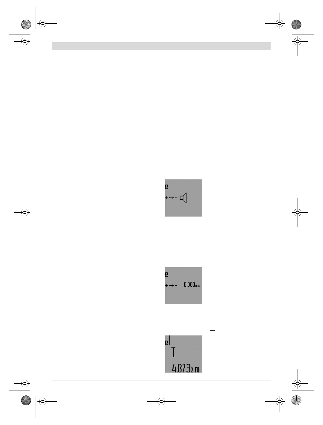
Audio Signal
To switch the audio signal on and off,
press the function-mode button 3 un-
til the “audio-signal adjustment” indi-
cation appears on the display. Select
the required setting by pressing the
plus button 6 or the minus button 12.
The selected audio-signal adjustment
is retained when switching the measuring tool off and on.
Changing the Unit of Measure
For indication of the measured values, the unit of measure can
be changed at any time.
The following units of measure are possible:
– Length measurement: m, cm, mm,
– Area/surface measurement: m
2
,
– Volume measurement: m
3
.
To to change the unit of measure,
press the function-mode button 3 un-
til the “change unit of measure” indi-
cation appears on the display. Select
the required unit of measure by
pressing the plus button 6 or the mi-
nus button 12.
Measuring Functions
Simple Length Measurement
For length measurements, press button 4 until the “length
measurement” indication appears on the display.
Press the measuring button 7 once
for sighting and once more to take the
measurement.
The measured value is displayed in
the result line c.
OBJ_BUCH-947-007.book Page 19 Friday, July 8, 2016 10:44 AM
20 | English
1 609 92A 1YW | (8.7.16) Bosch Power Tools
For several subsequent length measurements, the last meas-
ured results are displayed in the measured-value lines a.
Continuous Measurement (Tracking)
For continuous measurements, the measuring tool can be
moved relative to the target, whereby the measuring value is
updated approx. every 0.5 seconds. In this manner, as an ex-
ample, you can move a certain distance away from a wall,
while the actual distance can always be read.
For continuous measurements, firstly select the length meas-
uring mode and then press the measuring button 7 until the
“indicator for continuous measurement” appears on the
display. The laser is switched on and the measurement starts
immediately.
The current measured value is dis-
played in the result line c.
Briefly pressing the measuring button
7 ends the continuous measurement.
The last measured value is displayed
in the result line c. Pressing the meas-
uring button 7 for several seconds re-
starts a continuous measuring run.
Continuous measurement automatically switches off after
5 min. The last measured value remains indicated in the result
line c.
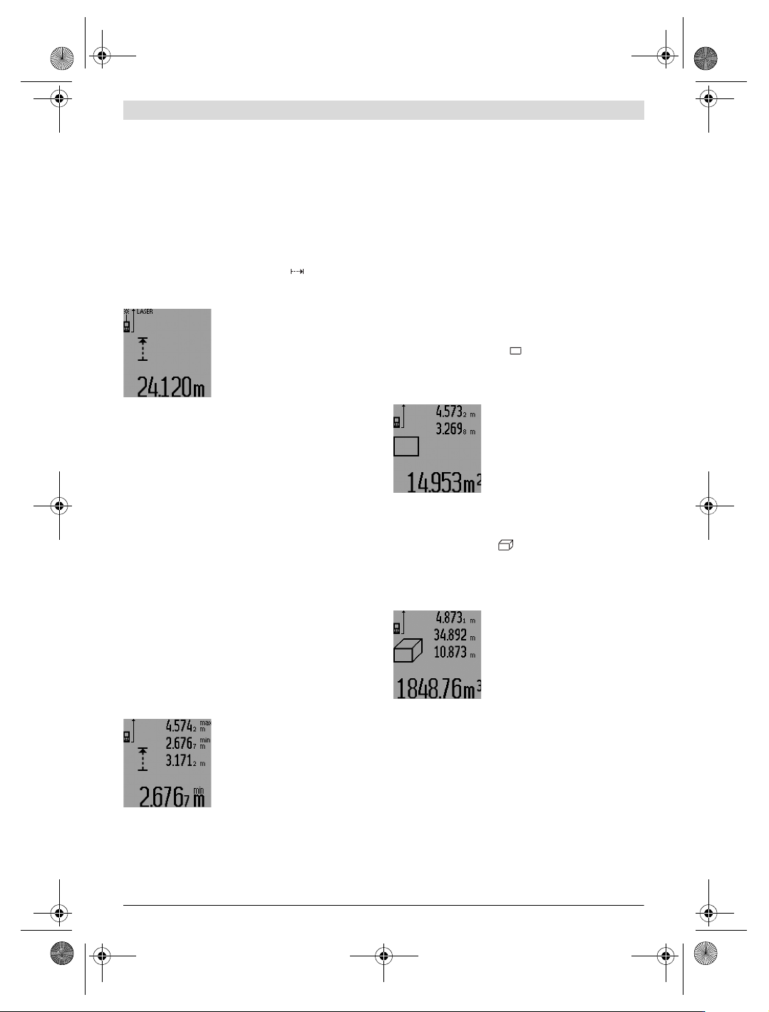
Minimum/Maximum Measurement (see figure F–G)
The minimum measurement is used to determine the shortest
distance from a fixed reference point. It is used, as an exam-
ple, for determining plumb lines or horizontal partitions.
The maximum measurement is used to determine the greatest
distance from a fixed reference point. It is used, as an exam-
ple, for determining diagonals.
For simple minimum/maximum measurement, firstly select
“length measurement mode” and then press button 13. “min”
is displayed in result line c for minimum measurement. For
maximum measurements, press button 13 again, so that
“max” is displayed in the result line. Then press the measur-
ing button 7. The laser is switched on and the measurement
starts.
Move the laser back and forth over the requested target (e.g.,
the room corner for determining the diagonal) in such a man-
ner that the reference point of the measurement (e.g., the tip
of the positioning pin 18) always remains at the same loca-
tion.
Depending on the set mode, the mini-
mum or maximum value is displayed
in the result line c. It is always over-
written, when the current length
measurement value is less than the
present minimal or larger than the
present maximal value. The maximal
(“max”), the minimal (“min”) and
the current measuring value are displayed in the measured-
value lines a.
To end the minimum/maximum measurement, briefly press
the measuring button 7. Pressing the measuring button again
starts a new measurement.
The minimum/maximum measurement can also be used for
length measurements within other measuring modes (e.g. ar-
ea/surface measurement). For this, press button 13 once for
minimal measurement and twice for maximal measurement
each time when determining individual measured values.
Then press the measuring button 7 to switch the laser beam
on. Move the measuring tool in such a manner that the desired
minimum or maximum value is measured, and press the
measuring button 7 to take over the minimum or maximum
value into the current calculation.
For time-delayed length measurements and when in mark-out
mode, minimum/maximum measurements are not possible.
The minimum/maximum measurement automatically switch-
es off after 5 min.
Area Measurement
For area/surface measurements, press button 4 until the indi-
cator for area measurement appears on the display.
Afterwards, measure the length and the width, one after an-
other, in the same manner as a length measurement. The laser
beam remains switched on between both measurements.
Upon completion of the second meas-
urement, the surface is automatically
calculated and displayed in the result
line c. The individual measured values
are displayed in the measured-value
lines a.
Volume Measurement
For volume measurements, press button 4 until the indicator
for volume measurement appears on the display.
Afterwards, measure the length, width and the height, one af-
ter another, in the same manner as for a length measurement.
The laser beam remains switched on between all three meas-
urements.
Upon completion of the third meas-
urement, the volume is automatically
calculated and displayed in the result
line c. The individual measured values
are displayed in the measured-value
lines a.
Values above 999999 m
3
cannot be indicated; “ERROR” and
“––––” appear on the display. Divide the volume to be
measured into individual measurements; their values can
then be calculated separately and then summarized.
Indirect Length Measurement (see figures H–K)
The indirect length measurement is used to measure distanc-
es that cannot be measured directly because an obstacle
would obstruct the laser beam or no target surface is available
as a reflector. Correct results are achieved only when the right
angles required for the respective measurement are exactly
adhered to (Pythagorean Theorem).
Pay attention that the reference point of the measurement
(e.g. the rear edge of the measuring tool) remains exactly at
OBJ_BUCH-947-007.book Page 20 Friday, July 8, 2016 10:44 AM
English | 21
Bosch Power Tools 1 609 92A 1YW | (8.7.16)
the same location for all individual measurements within a
measuring sequence (exception: trapezium measurements).
The laser beam remains switched on between the individual
measurements.
For indirect length measurements, four measuring modes are
available. Each measuring mode can be used for determining
different distances. To select the measuring mode, press the
function-mode button 3 until the symbol of the desired meas-
uring mode is indicated on the display.
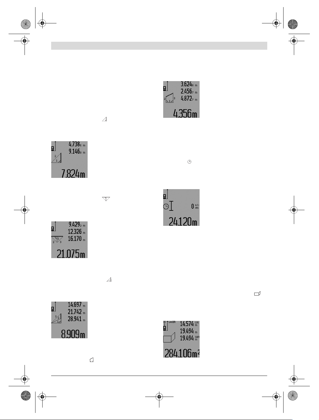
a) Simple Pythagoras Measurement (see figure H)
Press the function-mode button 3 until the indication for sim-
ple Pythagoras measurement appears on the display.
Measure distances “1” and “2” in this sequence with a length
measurement. Pay attention that a right angle exists between
distance “1” and the sought distance “E”.
Upon completion of the last measure-
ment, the result for the sought dis-
tance “E” is displayed in the result
line c. The individual measured values
are displayed in the measured-value
lines a.
b) Double Pythagoras Measurement (see figure I)
Press the function-mode button 3 until the indication for dou-
ble Pythagoras measurement appears on the display.
Measure distances “1”, “2” and “3” in this sequence with a
length measurement. Pay attention that a right angle exists
between distance “1” and the sought distance “E”.
Upon completion of the last measure-
ment, the result for the sought dis-
tance “E” is displayed in the result
line c. The individual measured values
are displayed in the measured-value
lines a.
c) Combined Pythagoras Measurement (see figure J)
Press the function-mode button 3 until the indication for com-
bined Pythagoras measurement appears on the display.
Measure distances “1”, “2” and “3” in this sequence with a
length measurement. Pay attention that a right angle exists
between distance “1” and the sought distance “E”.
Upon completion of the last measure-
ment, the result for the sought dis-
tance “E” is displayed in the result
line c. The individual measured values
are displayed in the measured-value
lines a.
d) Trapezium Measurement (see figure K)
Press the function-mode button
3 until the indication for tra-
pezium measurement appears on the display.
Measure distances “1”, “2” and “3” in this sequence with a
length measurement. Pay attention that the measurement of
distance “3” starts exactly at the end point of distance “1”
and that a right angle exists between distances “1” and “2” as
well as between “1” and “3”.
Upon completion of the last measure-
ment, the result for the sought dis-
tance “E” is displayed in the result
line c. The individual measured values
are displayed in the measured-value
lines a.
Time-delayed Length Measurement
Time-delayed length measurement is helpful e.g. when meas-
uring at hard to reach locations or when movements of the
measuring tool during measuring are to be prevented.
For a time-delayed length measurement, press function-
mode button 3 until the indicator for time-delayed length
measurement appears on the display.
The time period from the actuation until the measurement
takes place is displayed in the measured-value line a. The time
period can be adjusted between 1 s and 60 s by pressing the
plus button 6 or the minus button 12.
Then press the measuring button 7 to
switch the laser beam on and aim at
the target point. Press the measuring
button 7 again to actuate the meas-
urement. The measurement takes
place after the set time period. The
measured value is displayed in the re-
sult line c.
The addition and subtraction of measuring results as well as
minimum/maximum measurements are not possible for time-
delayed length measurements.
Wall Surface Measurement (see figure L)
The wall surface measurement is used to determine the sum
of several individual surfaces with a common height.
In the example shown, the total surface of several walls that
have the same room height A, but different lengths B, are to
be determined.
For wall surface measurements, press the function-mode but-
ton 3 until the indicator for wall surface measurement ap-
pears on the display.
Measure the room height A as for a length measurement. The
measured value (“cst”) is displayed in the top measured-val-
ue line a. The laser remains switched on.
Afterwards, measure length B
1
of the
first wall. The surface is automatically
calculated and displayed in the result
line c. The length measurement value
is displayed in the centre measured-
value line a. The laser remains
switched on.
1
2
1
32
1
3
2
1
3
2
OBJ_BUCH-947-007.book Page 21 Friday, July 8, 2016 10:44 AM