GLM250 VF激光测距仪数据表.pdf - 第24页
24 | English 1 609 92A 1YW | (8.7.1 6) Bosch Power Tools available camera tri pod. Tighte n t he measuring tool with the locking screw of the quick-change plate. Set the corresponding re ference level for measuremen t wi…
English | 23
Bosch Power Tools 1 609 92A 1YW | (8.7.16)
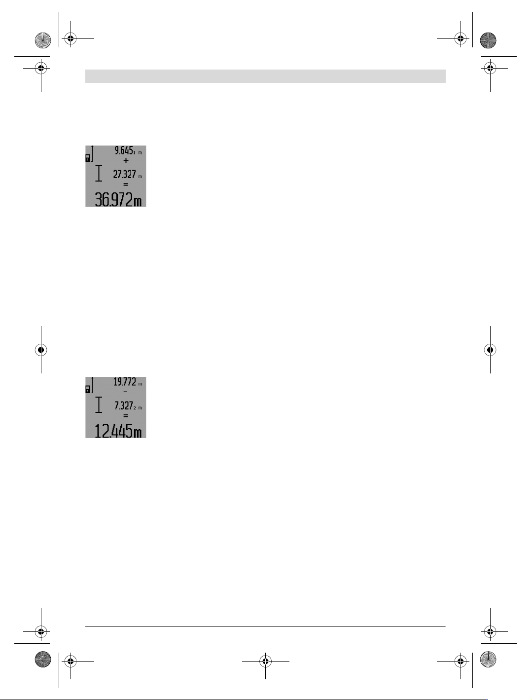
Adding Measured Values
To add measured values, firstly carry out any measurement or
select an entry from the measured-value list. Then press the
plus button 6. For confirmation, “+” appears on the display.
Then carry out a second measurement or select another entry
from the measured-value list.
To call up the sum of both measure-
ments, press the result button 5. The
calculation is indicated in the meas-
ured-value lines a, and the sum in the
result line c.
After calculation of the sum, further
measured values or measured-value
list entries can be added to this result when pressing the plus
button 6 prior to each measurement. Pressing the result but-
ton 5 ends the addition.
Notes on the addition:
– Mixed length, area and volume values cannot be added to-
gether. For example, when a length and area value are add-
ed, “ERROR” briefly appears on the display after pressing
the result button 5. Afterwards, the measuring tool switch-
es back to the last active measuring mode.
– For each calculation, the result of one measurement is
added (e.g. the volume value); for continuous measure-
ments, this would be the displayed measured value in re-
sult line c. The addition of individual measured values from
the measured-value lines a is not possible.
– For time-delayed length measurements and when in mark-
out mode, additions are not possible; when changing to
these modes, begun additions are interrupted.
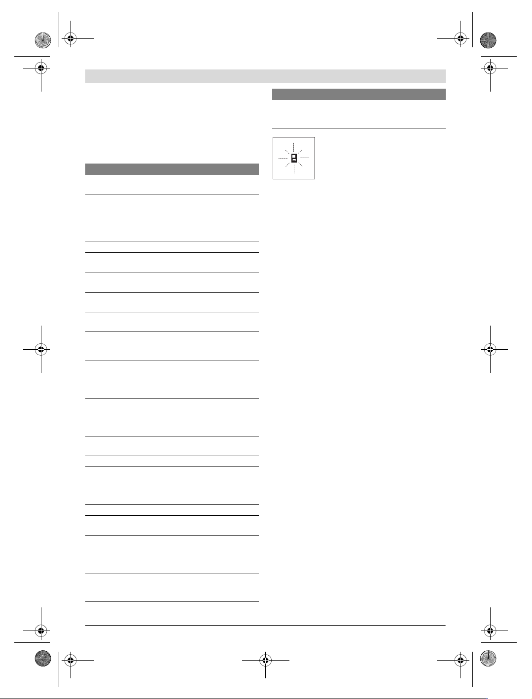
Subtracting Measured Values
To subtract measuring values, press
minus button 12; For confirmation,
“–” is indicated on the display. The
further procedure is analog to
“Adding Measured Values”.
Working Advice
General Information
The reception lens 26 and the laser beam outlet 27 must not
be covered when taking a measurement.
The measuring tool must not be moved while taking a meas-
urement (except for continuous measurements, mini-
mum/maximum measurements and when in mark-out mode).
Therefore, place the measuring tool, as far as this is possible,
against or on a firm stop or supporting surface.
Influence Effects on the Measuring Range
The measuring range depends upon the light conditions and
the reflection properties of the target surface. For improved
visibility of the laser beam when working outdoors and when
the sunlight is intense, use the laser viewing glasses 31 (ac-
cessory) and the laser target plate 32 (accessory), or shade
off the target surface.
Influence Effects on the Measuring Result
Due to physical effects, faulty measurements cannot be ex-
cluded when measuring on different surfaces. Included here
are:
– Transparent surfaces (e.g., glass, water),
– Reflecting surfaces (e.g., polished metal, glass),
– Porous surfaces (e.g. insulation materials),
– Structured surfaces (e.g., roughcast, natural stone).
If required, use the laser target plate 32 (accessory) on these
surfaces.
Furthermore, faulty measurements are also possible when
sighting inclined target surfaces.
Also, air layers with varying temperatures or indirectly re-
ceived reflections can affect the measured value.
Measuring with the Positioning Pin
(see figures B, C, F and G)
The positioning pin 18 is suitable for measuring out of corners
(diagonal within a space) or from hard to reach areas, such as
from roller-shutter rails.
Press on the positioning pin latch 1 to fold it in or out, or
change its position.
For measurements starting from outer corners, fold the posi-
tioning pin aside; for measurements from the rear edge of the
positioning pin on, fold it out to the rear.
For measurements with the positioning pin, adjust the refer-
ence plane accordingly by pressing button 8 (for measure-
ments with the positioning pin aside, set to measuring from
the rear edge of the measuring tool).
Aligning with the Spirit Level
The spirit level 14 allows for simple levelling of the measuring
tool. This allows for easier sighting of target surfaces, espe-
cially over longer distances.
In combination with the laser beam, the spirit level 14 is not
suitable for levelling.
Sighting with the Optical Sight (GLM 250 VF)
(see figure N)
The sighting line through the optical sight and the laser beam
run parallel to each other. This allows for precise sighting over
long distances, when the laser dot is no longer visible with the
naked eye.
For sighting, view through the viewfinder of the optical sight
10. Take care that the optical sight window 25 is not obstruct-
ed and clean.
Note: For close vicinities, the actual and the displayed target
point are not identical.
Sighting with the Alingment Aid (see figure O)
The alignment aid 24 supports sighting over larger distances.
For this, view alongside the alignment aid on the side of the
measuring tool. The laser beam runs parallel to this sighting
line.
Working with the Tripod (Accessory)
The use of a tripod is particularly necessary for larger distanc-
es. Position the measuring tool with the 1/4" thread 21 onto
the quick-change plate of the tripod 30 or a commercially
OBJ_BUCH-947-007.book Page 23 Friday, July 8, 2016 10:44 AM
24 | English
1 609 92A 1YW | (8.7.16) Bosch Power Tools
available camera tripod. Tighten the measuring tool with the
locking screw of the quick-change plate.
Set the corresponding reference level for measurement with
a tripod by pushing button 8 (the reference level is the
thread).
Troubleshooting – Causes and Corrective Meas-
ures
The measuring tool monitors the correct
function for each measurement. When a de-
fect is determined, only the symbol shown
aside flashes in the display. In this case, or
when the above mentioned corrective
measures cannot correct an error, have the
measuring tool checked by an after-sales service agent for
Bosch power tools.
Accuracy Check of the Measuring Tool
The accuracy of the measuring tool can be checked as follows:
– Select a permanently unchangeable measuring section
with a length of approx. 1 to 10 metres; its length must be
precisely known (e.g. the width of a room or a door open-
ing). The measuring distance must be indoors; the target
surface for the measurement must be smooth and reflect
well.
–Measure the distance 10 times after another.
The deviation of the individual measurements from the mean
value must not exceed ±1.5 mm (max.). Log the measure-
ments, so that you can compare their accuracy at a later point
of time.
Maintenance and Service
Maintenance and Cleaning
Store and transport the measuring tool only in the supplied
protective pouch.
Keep the measuring tool clean at all times.
Do not immerse the measuring tool in water or other fluids.
Wipe off debris using a moist and soft cloth. Do not use any
cleaning agents or solvents.
Maintain the reception lens 26 in particular, with the same
care as required for eye glasses or the lens of a camera.
In all correspondence and spare parts orders, please always
include the 10-digit article number given on the type plate of
the measuring tool.
In case of repairs, send in the measuring tool packed in its
protective pouch 28.
After-sales Service and Application Service
Our after-sales service responds to your questions concern-
ing maintenance and repair of your product as well as spare
parts. Exploded views and information on spare parts can al-
so be found under:
www.bosch-pt.com
Bosch’s application service team will gladly answer questions
concerning our products and their accessories.
In all correspondence and spare parts orders, please always
include the 10-digit article number given on the nameplate of
the product.
Cause Corrective Measure
Temperature warning indicator (i) flashing;
measurement not possible
The measuring tool is outside the
operating temperature range from
–10°C to +50°C (in the
continuous measurement function
up to +40 °C).
Wait until the measuring
tool has reached the
operating temperature
Battery low indicator (f) appears
Battery voltage decreasing
(measurement still possible).
Replace batteries/
rechargeable batteries
Battery low indicator (f) flashing; measurement not
possible
Battery voltage too low Replace batteries/
rechargeable batteries
The indications “ERROR” and “–––––” are indicated in
the display
The angle between the laser beam
and the target is too acute.
Enlarge the angle
between the laser beam
and the target
The target surface reflects too
intensely (e.g. a mirror) or
insufficiently (e. g. black fabric), or
the ambient light is too bright.
Work with the laser
target plate 32
(accessory)
The laser beam outlet 27 or the
reception lens 26 are misted up
(e.g. due to a rapid temperature
change).
Wipe the laser beam
outlet 27 and/or the
reception lens 26 dry
using a soft cloth
Calculated value is greater than
999999 m/m
2
/m
3
.
Divide calculation into
intermediate steps
The indication “ERROR” flashes at the top in the display
Addition/Subtraction of measured
values with different units of
measure
Only add/subtract
measured values with
the same units of
measure
Measuring result not plausible
The target surface does not reflect
correctly (e.g. water, glass).
Cover off the target
surface
The laser beam outlet 27 or the
reception lens 26 are covered.
Make sure that the laser
beam outlet 27 or the
reception lens 26 are
unobstructed
Obstruction in path of laser beam Laser point must be
completely on target
surface.
Wrong reference level set Select reference level
that corresponds to
measurement
Cause Corrective Measure
OBJ_BUCH-947-007.book Page 24 Friday, July 8, 2016 10:44 AM
Français | 25
Bosch Power Tools 1 609 92A 1YW | (8.7.16)
Great Britain
Robert Bosch Ltd. (B.S.C.)
P.O. Box 98
Broadwater Park
North Orbital Road
Denham
Uxbridge
UB 9 5HJ
At www.bosch-pt.co.uk you can order spare parts or arrange
the collection of a product in need of servicing or repair.
Tel. Service: (0344) 7360109
E-Mail: boschservicecentre@bosch.com
Ireland
Origo Ltd.
Unit 23 Magna Drive
Magna Business Park
City West
Dublin 24
Tel. Service: (01) 4666700
Fax: (01) 4666888
Australia, New Zealand and Pacific Islands
Robert Bosch Australia Pty. Ltd.
Power Tools
Locked Bag 66
Clayton South VIC 3169
Customer Contact Center
Inside Australia:
Phone: (01300) 307044
Fax: (01300) 307045
Inside New Zealand:
Phone: (0800) 543353
Fax: (0800) 428570
Outside AU and NZ:
Phone: +61 3 95415555
www.bosch.com.au
Republic of South Africa
Customer service
Hotline: (011) 6519600
Gauteng – BSC Service Centre
35 Roper Street, New Centre
Johannesburg
Tel.: (011) 4939375
Fax: (011) 4930126
E-Mail: bsctools@icon.co.za
KZN – BSC Service Centre
Unit E, Almar Centre
143 Crompton Street
Pinetown
Tel.: (031) 7012120
Fax: (031) 7012446
E-Mail: bsc.dur@za.bosch.com
Western Cape – BSC Service Centre
Democracy Way, Prosperity Park
Milnerton
Tel.: (021) 5512577
Fax: (021) 5513223
E-Mail: bsc@zsd.co.za
Bosch Headquarters
Midrand, Gauteng
Tel.: (011) 6519600
Fax: (011) 6519880
E-Mail: rbsa-hq.pts@za.bosch.com
Disposal
Measuring tools, accessories and packaging should be sorted
for environmental-friendly recycling.
Do not dispose of measuring tools and batteries/rechargea-
ble batteries into household waste!
Only for EC countries:
According to the European Guideline
2012/19/EU, measuring tools that are no
longer usable, and according to the Europe-
an Guideline 2006/66/EC, defective or
used battery packs/batteries, must be col-
lected separately and disposed of in an en-
vironmentally correct manner.
Battery packs/batteries no longer suitable for use can be di-
rectly returned at:
Great Britain
Robert Bosch Ltd. (B.S.C.)
P.O. Box 98
Broadwater Park
North Orbital Road
Denham
Uxbridge
UB 9 5HJ
At www.bosch-pt.co.uk you can order spare parts or arrange
the collection of a product in need of servicing or repair.
Tel. Service: (0344) 7360109
E-Mail: boschservicecentre@bosch.com
Subject to change without notice.
Français
Avertissements de sécurité
Pour une utilisation sans danger et en toute
sécurité de l’appareil de mesure, lisez at-
tentivement toutes les instructions et te-
nez-en compte. Si l’appareil de mesure
n’est pas utilisé conformément aux pré-
sentes instructions, les dispositifs de pro-
tection intégrés dans l’appareil sont sus-
ceptibles d’être endommagés. Faites en
sorte que les étiquettes d’avertissement se trouvant sur
l’appareil de mesure restent toujours lisibles. CONSER-
VEZ CES INSTRUCTIONS DANS UN LIEU SÛR ET REMET-
TEZ-LES À TOUT NOUVEL UTILISATEUR DE L’APPAREIL DE
MESURE.
Attention – si d’autres dispositifs d’utilisation ou
d’ajustage que ceux indiqués ici sont utilisés ou si
OBJ_BUCH-947-007.book Page 25 Friday, July 8, 2016 10:44 AM