JX-350_EPU使用说明书.pdf - 第100页
EPU Instruction M anual C hapter 4 Creating a Production Progr am 4- 52 (6) O ther dim ensions 1) Pick depth Enter the heig ht f rom the nozzle pick surf ace to t he top surf ace of the component. Usually , the def ault …
EPU Instruction Manual Chapter 4 Creating a Production Program
4-51
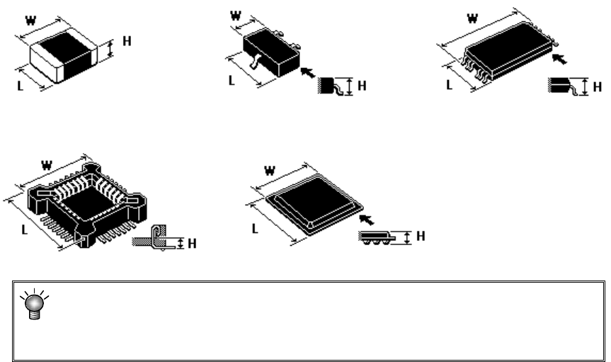
(5) Outer dimensions
Enter outer dimensions of component matched to each component type.
Enter them by referring to the component illustration shown in the lower left part of
the form screen. Note that there are 2 cases, namely, one where the lead is
included and the other where the lead is not included, depending on the component
type.
The graphic data based on JUKI component feed angle definition 0° is displayed
according to "Component type."
Example: W = Outer dimension, horizontal
L = Outer dimension, vertical H: Component height
♦
Square chip ♦SOT ♦T-SOP
♦ Socket ♦BGA
If you enter the dimensions oppositely, that is, enter the width (horizontal) to the
“Length” field or vice versa, the system may not be able to center the component.
If a wrong component height is entered, a laser recognition error may be easily
caused by unstable laser measuring position.
EPU Instruction Manual Chapter 4 Creating a Production Program
4-52
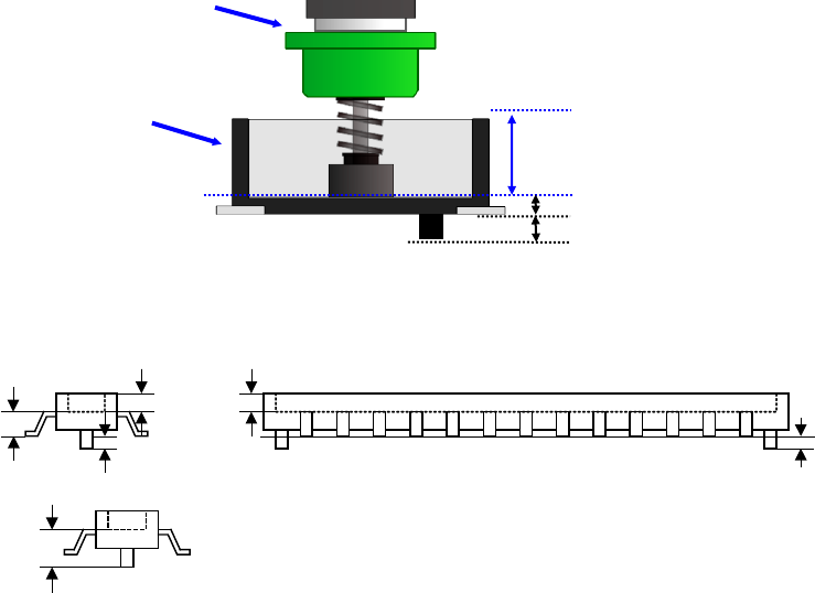
(6) Other dimensions
1) Pick depth
Enter the height from the nozzle pick surface to the top surface of the component.
Usually, the default value is used for operation.
2) Boss height
Enter the boss height (projection height on the bottom surface) of the connector.
Usually, the default value is used for operation.
Component height=Component height measured with laser-Boss height
Example) If the picking surface of the nozzle is located at the lower position than the top
surface of the component, such as connector component, enter the distance from
the nozzle tip to the top surface of the component. In this case, the "Component
height" will be the distance from the nozzle tip to the bottom surface of the
component.
Nozzle
Connector
Component height
Pick depth
Boss height
Component height
Pick depth
Boss height
Boss height
Component height
measured with laser
EPU Instruction Manual Chapter 4 Creating a Production Program
4-53
(7) Centering method
Specify the method of obtaining the center of the component.
Select this method according to the component (in consideration of specifications,
accuracy, and tact). However, available centering methods are limited depending on
the component type.
* JX-350 is not applicable to the vision centering.
Component type
Laser
Component type
Laser
Square chip O TSOP2 O
Square chip p (LED) O BGA O
Melf O QFN O
Elec. Cap. (Aluminum electrolytic
capacitor)
O One-direction lead connector O
SOT O Two-direction lead connector O
Trimmer O Z-lead connector O
RNA (Network resistor) O J-lead socket O
SOP O Gull-wing socket O
HSOP O Socket with bumper O
SOJ O Other O
QFP O
GaAsFET O
PLCC O
PQFP O
TSOP O
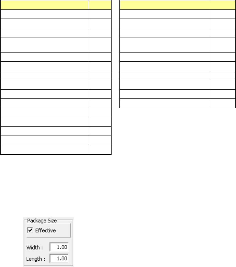
(8) Package size
When using the boss LED lens component, the package portion (body) may be in
contact with the disposal box when disposing of components or adjacent
components may interfere with each other when picking up components. Therefore,
enter the package size length (PL) and width (PW).
You can enter the package size length and width when [Effective] is checked on.
(9) <OK> button and <Cancel> button
When you press the <OK> button, the system validates your editing and quits the
“Form” screen.
When you press the <Cancel> button, the system discards your editing and quits the
“Form” screen.
When you quit the “Form” screen, the system redisplays the “Placement” data screen
if you invoke the “Form” screen from the “Placement” screen, or the “Component”
data list screen if you invoke the “Form” screen from the “Component” data list
screen.
If you quit the “Form” screen with any method other than buttons (by the menu
command or by selecting a tab), the system executes the same process as when you
press the <OK> button.