JX-350_EPU使用说明书.pdf - 第63页
EPU Instruction M anual C hapter 4 Creating a Production Progr am 4- 15 (1 2) Placement range every clamping Enter a placement rang e at f irst clamp when clamping a larg e - shape PW B whose PW B external size X exceeds…
EPU Instruction Manual Chapter 4 Creating a Production Program
4-14
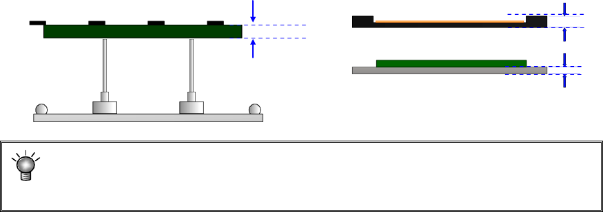
(10) PWB thickness
Enter the thickness of a PWB. The value you entered here is used to determine how
much the system should move up the support table when it is centering a PWB.
If an incorrect value is entered, the support pin pushes the PWB too much, thereby
damaging the PWB, and the placement may lose uniformity because the support pin
does not touch the PWB.
(11) Back height
Enter the height of the tallest component among the components placed on the back
side of a PWB (you have to enter a value that causes components on the back side
not to interfere with the support pin if components are placed on both sides of a
PWB).
* Not used in JX-350.
PWB thickness
EPU Instruction Manual Chapter 4 Creating a Production Program
4-15
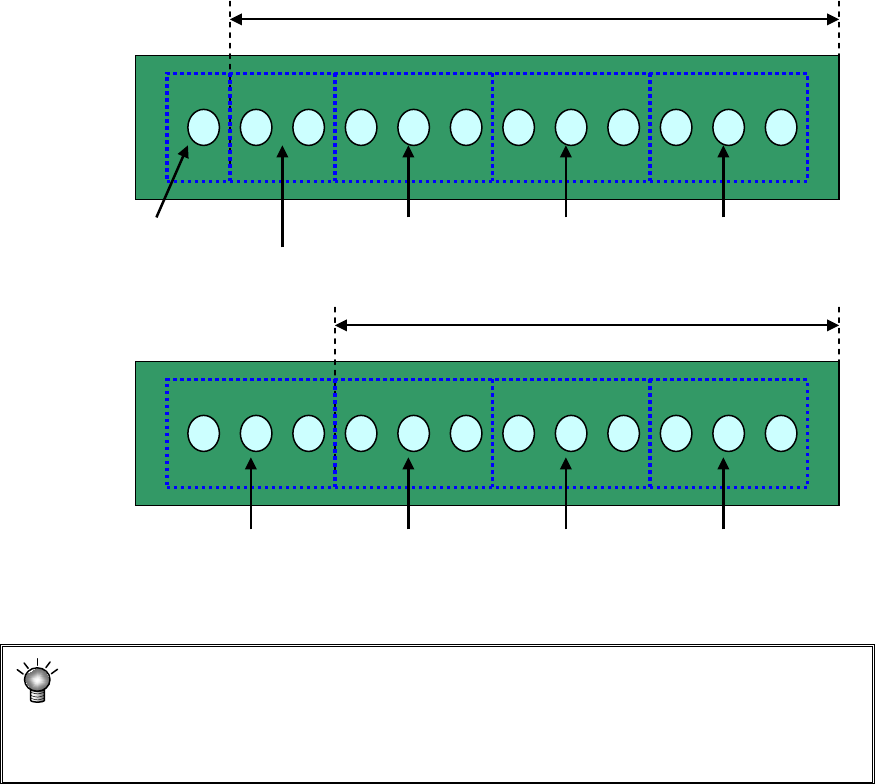
(12) Placement range every clamping
Enter a placement range at first clamp when clamping a large-shape PWB whose
PWB external size X exceeds 650 mm. When the number of components to be
placed is small, the tact may be improved by changing the placement range every
clamping.
[Three components can be picked up at once.]
Adjusting the placement range every clamping will reduce the pickup count from 5 to
4. This greatly improves the tact.
* For using a large-shaped PWB whose external length X exceeds 1200mm
(option):
If the placement range at first clamp is changed from 650 (mm), a PWB range that
cannot be placed may occur. So, do not change this placement range.
Placement range at first clamp: 650 mm (initial value)
#1 Pickup/
placement
#2 Pickup/
placement
#3 Pickup/
placement
#4 Pickup/
placement
#5 Pickup/
placement
#1 Pickup/
placement
#2 Pickup/
placement
#3 Pickup/
placement
#4 Pickup/
placement
Placement range at first clamp: 550 mm
EPU Instruction Manual Chapter 4 Creating a Production Program
4-16
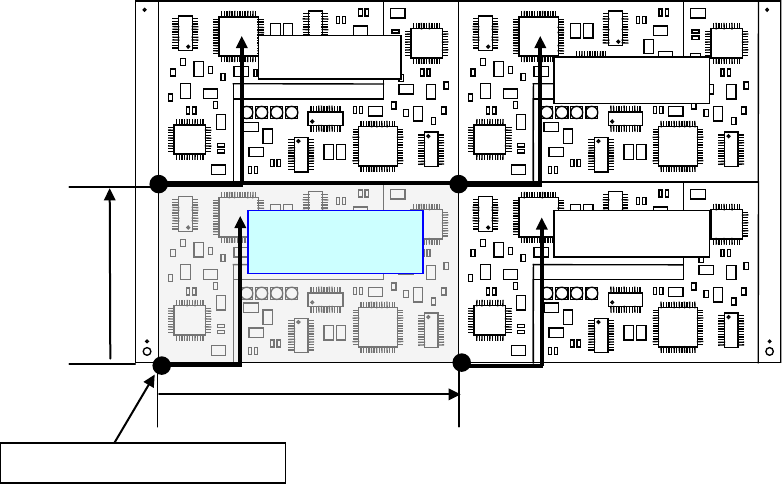
4.1.2.2.3 Dimension settings (multi-circuit PWB)
When a PWB in which multiple same circuits are arranged on a single PWB is called
“multi-circuit PWB.” As placement data, create the data for a single circuit (this circuit is
called “reference circuit”) and enter the circuit arrangement information (inter-circuit pitch,
number of circuits, etc.) into the PWB data.
Two types of multi-plane PWBs are available: matrix circuit board and non-matrix circuit
board
Second circuit
Fourth circuit
Pitch X
Pitch Y
Third circuit
Reference circuit
Origin of the reference circuit