JX-350_EPU使用说明书.pdf - 第72页
EPU Instruction M anual C hapter 4 Creating a Production Progr am 4- 24 1) PWB dim ensions: Enter the dimensions of the PW B including all circuits. 2) Refer ence hole positi on : * Not used in JX - 350. 3) PWB layout of…
EPU Instruction Manual Chapter 4 Creating a Production Program
4-23
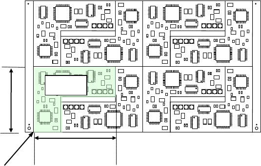
(2) Multi-plane non-matrix PWB
(set as “Non-matrix circuit” on the “Basic setting” screen)
The angle of each circuit is different from each other and the distance (pitch) between
circuits is not equal on this type of PWB (see the example on the next page).
The system places each circuit on a PWB one by one according to the specified X
and Y angles with regarding the PWB origin as the reference position. Therefore,
the system can handle the different pitch or the different circuit angle from other ones.
If you specify the same circuit pitch and angle, you can create PWB data for a
multi-plane matrix PWB also.
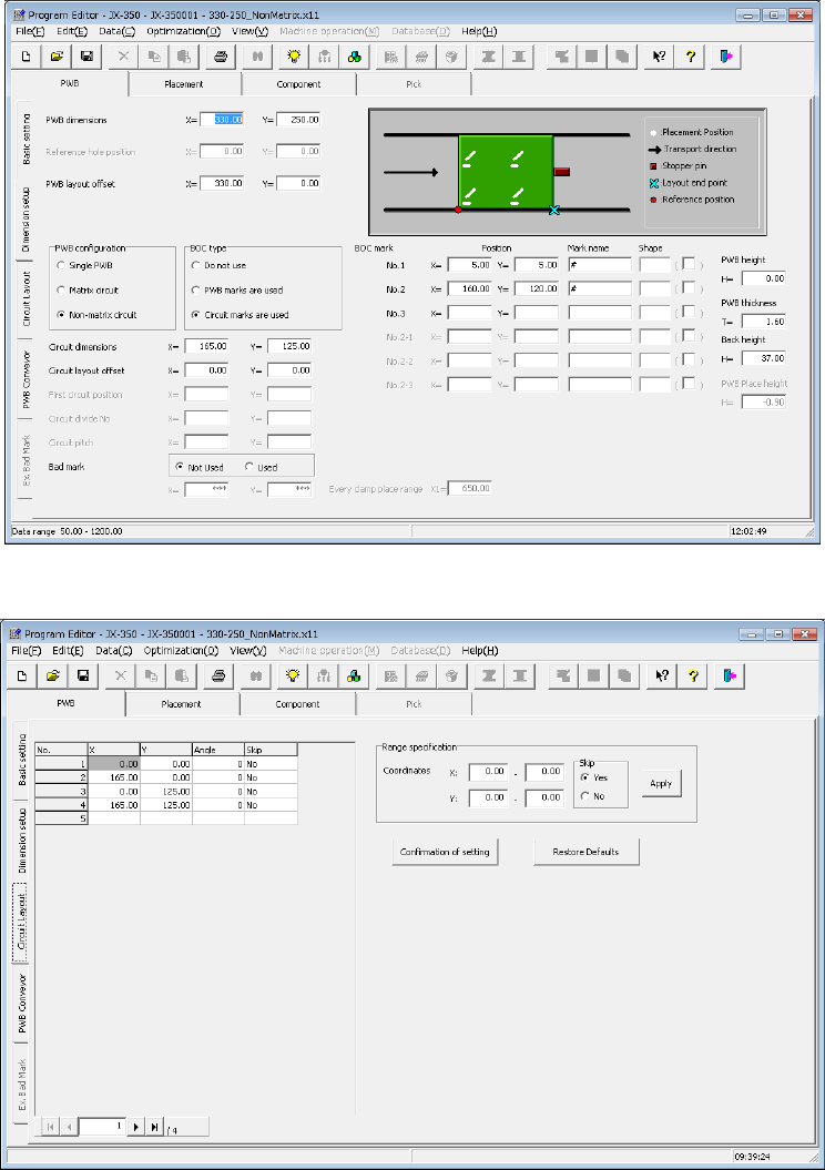
- Length setting screen
- Circuit layout screen
EPU Instruction Manual Chapter 4 Creating a Production Program
4-24
1) PWB dimensions:
Enter the dimensions of the PWB including all circuits.
2) Reference hole position:
* Not used in JX-350.
3) PWB layout offset:
In the same manner as a single-plane PWB, enter the position of the PWB layout
endpoint viewed from the PWB origin.
4) PWB configuration:
Select the “Non-matrix circuit” radio button.
5) BOC type:
Select the radio button in the same manner as when you select the “Matrix circuit”
in the “PWB configuration” column.
♦ Do not use: Select this radio button if you do not use a BOC mark at all.
♦ PWB marks/ref. ckt marks are used: Select this radio button if you are to
correct the coordinates of a component placement position with using BOC
marks.
♦ Circuit marks are used: Select this radio button if you are to correct a
component placement position with recognizing BOC marks on each circuit of
a multi-plane (circuit) board. When there are many circuits on a board, this
selection requires much time to recognize marks, but the accuracy of
component placement tends to be higher than that when you select the “PWB
marks/ref. ckt marks are used” radio button.
6) Circuit dimensions:
Enter the dimensions of a circuit (the dimensions that include all placement
coordinates).
Example)
7) Circuit layout offset:
Enter the distance from the circuit origin of the reference circuit to the left bottom
corner (this is an always fixed point regardless of the PWB transport direction) of
the reference circuit.
8) First circuit position, Circuit divide No., Circuit pitch:
You do not have to set these fields when you select the “Non-matrix circuit” radio
button in the “PWB configuration” (they are not available).
When you select the “Matrix circuit” radio button, enter a value in each field.
Circuit dimension X
Circuit dimension Y
Circuit layout offset
Reference
circuit
EPU Instruction Manual Chapter 4 Creating a Production Program
4-25
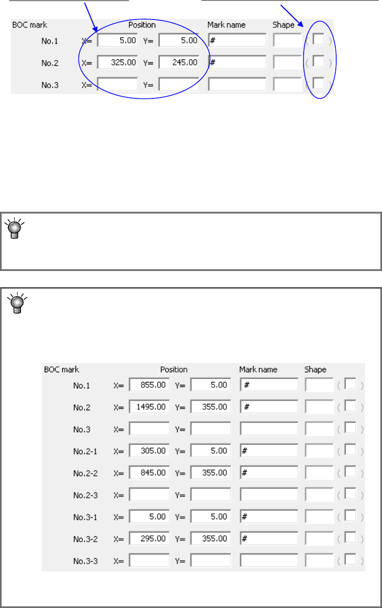
9) BOC mark position, Mark name, Shape:
Enter the distance from the PWB origin or the circuit origin to the center of a BOC
mark.
Enter the “Mark name” and “Shape” fields in the same manner as a single-plane
PWB (“Single PWB” as the “PWB configuration”).
♦ Using 2 points: It is possible to correct the difference between the design dimensions
and the actual dimensions (measured dimensions) and the rotation direction error.
For the third point, leave the field blank.
When there are multiple marks on the PWB, select 2 points on the diagonal lines in
all the placement range.
♦ For using 3 points: In addition to the case of two points, the perpendicularity distortion
between the X axis and Y axis can be corrected.
When “PWB marks are used” is selected as “BOC type” on the “Basic
setting” screen, this is the distance from the PWB origin to a BOC mark.
When “Circuit marks are used” is selected, this is the distance from the
circuit origin to a BOC mark.
For using a long PWB:
For a large-shaped PWB whose external length X exceeds 650mm, set
the first and second BOC marks; for an optional large-shaped PWB whose
external length X exceeds 1200mm, set the first, second and third BOC
marks.
However, if the circuit is divided in the X direction and circuit BOC exists,
an error may be displayed at the start of production, disabling production.
JX-350 EPU is not applicable to the teaching.
Enter the X and Y coordinates.