JX-350_EPU使用说明书.pdf - 第86页
EPU Instruction M anual C hapter 4 Creating a Production Progr am 4- 38 4.1.3.2 Entry items Enter a value in each of the “ Component ID, ” “ X, ” “ Y, ” “ Ang le ” and “ Com ponent name ” fields. The corr esponding initi…
EPU Instruction Manual Chapter 4 Creating a Production Program
4-37
4.1.3 Placement data
Enter information on the coordinates of positions on which the system is to place
components.
For a multi-plane PWB, enter the information on the “reference circuit.”
Number of component placements:
You can enter total of 10,000 placements regardless of the PWB type,
normal or divided type.
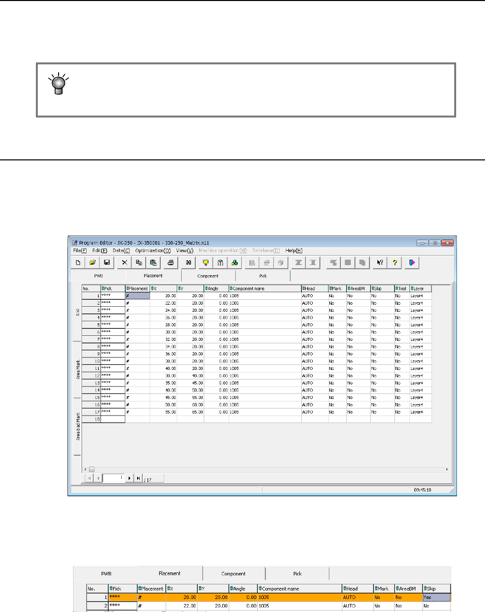
4.1.3.1 Viewing the placement data screen
When you click the “Placement” tab displayed on the screen after creating PWB data
completely, the “Placement” data screen for creating Placement data (the following figure
is an example indicating that Placement data was already created) appears on the
screen.
When any skip setting (including component data skip setting) is performed, the indication
is changed into orange as shown below.

EPU Instruction Manual Chapter 4 Creating a Production Program
4-38
4.1.3.2 Entry items
Enter a value in each of the “Component ID,” “X,” “Y, ” “Angle” and “Component name”
fields. The corresponding initial value is automatically entered in the other fields (the
“Head,” “Mark,” “AreaBM,” “Skip,” “Trial” and “Layer” fields). Change the value(s) in
these fields when necessary only.
Note that each coordinate indicates the distance from the “PWB origin” determined on the
“PWB” data screen (“Circuit origin” of the reference circuit for a multi-plane PWB).
(1) Pick
The component pick-up position set when you open the “Placement” data list screen
is shown here.
An asterisk mark (“*”) appears when the component pick-up position is not
determined.
When there are multiple feeders for the same component, the pick position is
determined by executing optimization.
When there are not multiple feeders for the same component, the pick position is
determined without executing optimization.
When there are two or more pick data records for the same component type, the
pick-up position of the first one appears, and a plus mark (“+”) appears to the left of
this position. You cannot enter any value in this field.
(2) Component ID
Enter the placement location as a reference notation. Therefore, this does not have
any influence over placement.
When this item is entered, the default value is applied to each item in which the
default value can be entered, and then displayed.
You can enter up to 16 characters (alphanumeric characters only).
In addition, this item can be omitted by clicking another item (such as an X
coordinate) without entering any data.
In this case, a "#" mark will be entered here automatically.
(3) X and Y
Enter the placement position (X, Y). You can enter a value from the keyboard or
with a teaching operation.
* Be sure to perform a BOC alignment operation before teaching it.
As a coordinate, enter the distance from the “PWB origin” (or circuit origin for a
multi-plane PWB) determined on the “PWB” data screen to the component placement
position (center of a coordinate).
・Entry of an absolute position:
Enter a numeric value from a keyboard.
You can assign a sign, “+” or “–“ (minus) for a value.
・Entry of a relative position:
When you enter “++” before a numeric value, the entered value is added to a
value displayed in the field on which the cursor is located.
When you enter “—“ before numeric value, the entered value is subtracted
from a value displayed in the field on which the cursor is located.
When you enter “+=” before a numeric value, the entered value is added to a
value in the field one line above the field on which the cursor is located.
When you enter “-=” before a numeric value, the entered value is subtracted
from a value displayed in the field one line above the field on which the cursor
is located.
Note: You cannot enter a space between two symbols, ++, --, += or -=.
(4) Angle
Enter the component placement angle with regarding the “Supply angle” specified on
the “Component” data screen as the reference angle.
(See Section 4.1.4.2.2 (1) How to enter data if you select “Tape” as the “Packaging
style” )
EPU Instruction Manual Chapter 4 Creating a Production Program
4-39
(5) Component name
Enter the name of a component (up to 60 characters).
Each time a component name is entered, component data is created.
If the use of database is set when a component name is entered, the database is
searched. Then, if the same component name is detected, the component data is
fetched into the program.
Upper-case characters and lower-case characters are handled as the same data but
are indicated with distinction on the display unit.
If the component name is registered in the database in advance, it is replaced with a
component name of the registered characters in the database.
(If the component name is a new one, it is displayed as it is entered. If the
component name already exists, this existing component name is displayed.)
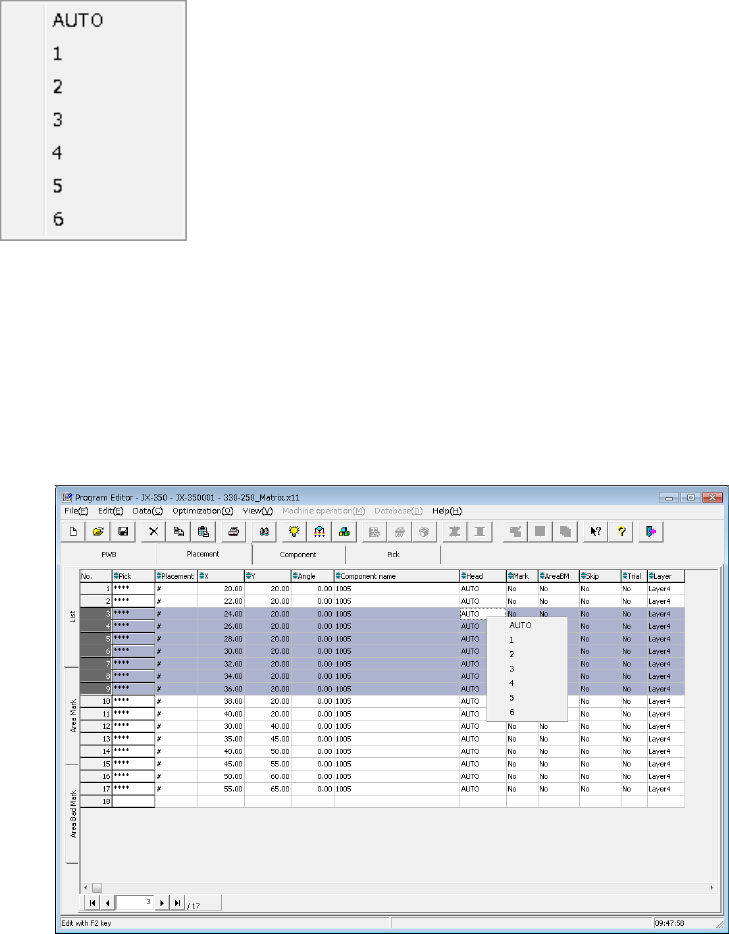
(6) Head
Specify a head to be used for placing a component on a board.
You can select from a pop-up menu a head that is to be used to place a component
when a PWB is produced in Input order.
“AUTO” is selected as the initial setting. When you execute the “Optimization” utility
after creating a production program, the system automatically selects the optimal
head.
To select a head, press the Edit key (<F2> key of the keyboard) or the right button of
a mouse to display the pop-up menu, and then select a head from this menu. If you
specify a head from the pop-up menu when two or more lines are selected, the heads
of all the selected records are changed to the head you specified. (The following
figure shows an example of multiple-line selection.)
Auto selection: A head to be used is automatically selected.
Head 1: Head 1 is specified.
Head 2: Head 2 is specified.
Head 3: Head 3 is specified.
Head 4: Head 4 is specified.
Head 5: Head 5 is specified.
Head 6: Head 6 is specified.