JX-350_EPU使用说明书.pdf - 第153页
EPU Instruction M anual C hapter 4 Creating a Production Progr am 4- 105 2) Calcul ating met hod for placement peak point S pecif y the calculating m ethod f or the starting point of feeder layout. a) A rr ange a feeder …
EPU Instruction Manual Chapter 4 Creating a Production Program
4-104
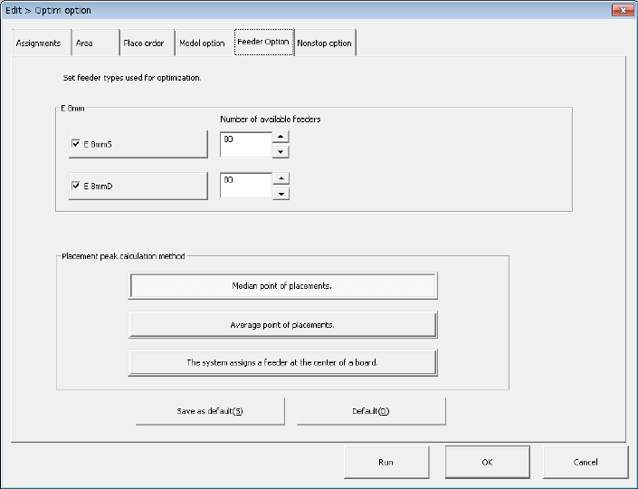
(5) Feeder Option
Set the calculating method for the feeder type to be used for optimization and feeder
layout.
1) Feeder type setting (E 8 mm)
For an electric feeder that has two or more feeder types for the same tape width,
set a “feeder type used for optimization.” When you select two or more feeder
types, the system uses the optimal feeder among the selected feeder types to
generate Pick data.
a) E 8mmS: Sets the upper limit of the number of 8-mm electric single tape
feeders.
b) E 8mmD: Sets the upper limit of the number of 8-mm electric double tape
feeders.
When two types of tape feeders, single and double, are used, the system sets the
number of 8-mm electric single tape feeders and that of 8-mm electric double
tape feeders to be assigned with the Optimization utility within the range you set
manually on the screen for setting the number of components. You can set a
value from 1 to 80 in both of the “Number of available feeders” edit boxes.
If the number you set manually on the screen for setting the number of
components exceeds the total of the number set in the “Number of available
feeders” for the “E 8mmS” and that for the “E 8mmD” when you press the <Run>
button, the Optimization utility cannot be executed.
EPU Instruction Manual Chapter 4 Creating a Production Program
4-105
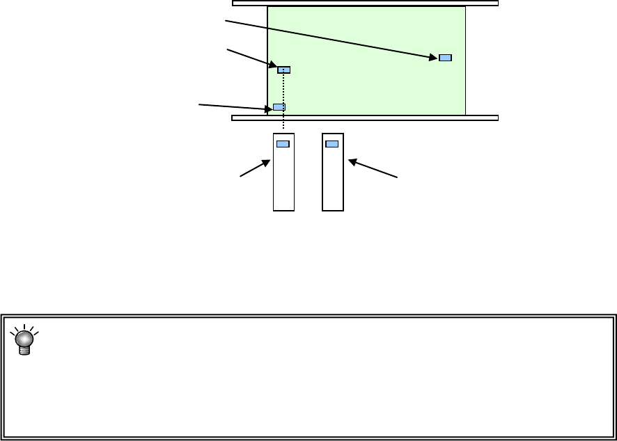
2) Calculating method for placement peak point
Specify the calculating method for the starting point of feeder layout.
a) Arrange a feeder in the mid-point of placement points
Arrange a feeder in a position close to the placement point that is a mid-point
counted from the smallest coordinate value when each placement point is
arranged in the order starting from the smallest coordinate value.
b) Arrange a feeder in the mean point of placement points.
Arrange a feeder in the position closest to the mean coordinate value of all the
placement points.
c) Arrange a feeder in the center point of the PWB.
Arrange a feeder in the position corresponding to the center coordinates of the
PWB.
• When there are many components and placement points are made uniform
over the PWB, both cases leads to the same result.
• Generally, when a part of placement points is separated among all the
placement points, "Mid-point" is advantageous. Otherwise, "Mean point" tends
to be advantageous.
(6) Non-stop option
* JX-350 is not applicable to the non-stop option.
The 2nd closest placement point
(Mid-point in this case)
The 3rd closest placement point
The first closest placement point
Feeder layout when "Feeder
layout in the mid-point" is
selected. (Layout on the base
of the mid-point)
Feeder layout when "Feeder layout in
the mean point" is selected
(Located on the basis of the mean
coordinates among placement points)
EPU Instruction Manual Chapter 4 Creating a Production Program
4-106
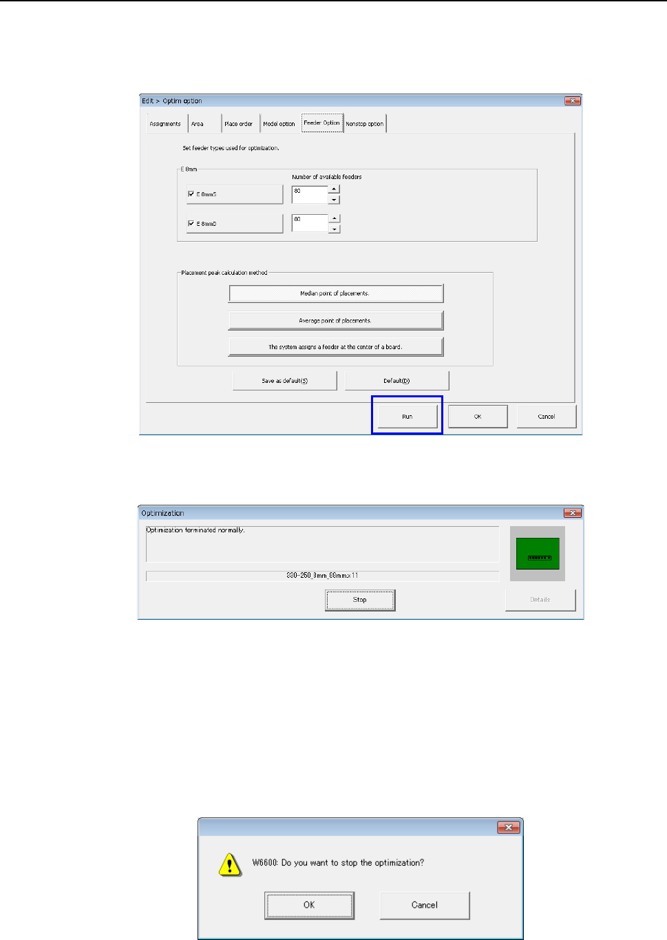
4.2.2 Executing the Optimization function
When you click the <Run> button on the “Optimization” conditions setting screen, the
system starts the optimization process.
The following screen is displayed while optimization is executed.
When the system finishes the Optimization function normally, the “Optimization” screen
disappears.
If an error occurs during optimization, the corresponding error message appears on the
screen.
When you click the <Stop> or <Skip> button during optimization, you can stop the
optimization.
The following confirmation message appears on the screen.