JX-350_EPU使用说明书.pdf - 第56页
EPU Instruction M anual C hapter 4 Creating a Production Progr am 4-8 4.1.2.2 Dimension setup A produc tion progr am uses coordinates to represent a component or m ark posit ion on a PW B. This origin of the “coor dinate…
EPU Instruction Manual Chapter 4 Creating a Production Program
4-7
(6) Circuit Mapping
This menu item allows you to specify whether to use the function for specifying a
circuit to be placed on a board. When you produce a multi-circuit board and you
know which circuit(s) is (are) not to be placed on a board, you can set it (them) so
that it (they) will not be placed on a board.
♦ Not Used:
Select this radio button when you produce PWBs without specifying which circuit is
not placed on a multi-circuit board. Select this radio button when you produce a
single-plane PWB also.
♦ Used:
Select this radio button when you produce a multi-circuit PWB with specifying which
circuit is to be placed on a board.
* See Section 4.1.2.3 “Circuit Layout” for description of the function for specifying a
circuit to be placed on a board.
When you select the “Used” radio button for the menu item “Bad mark” and select
the “Used” radio button for the menu item “Circuit Mapping”, both functions are
enabled. The system does not recognize any bad mark of circuits whose “Skip”
item is set to “Yes” on the “Circuit Layout” tab.
EPU Instruction Manual Chapter 4 Creating a Production Program
4-8
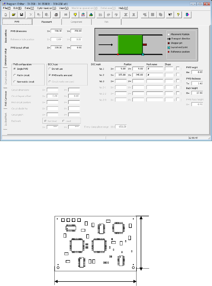
4.1.2.2 Dimension setup
A production program uses coordinates to represent a component or mark position on a
PWB.
This origin of the “coordinate system on a PWB” is called the “PWB origin.”
• You can set the PWB origin on a PWB or the desired position outside a PWB.
• If you use CAD data to create Placement data, use the origin of CAD data.
However, a mounter that places a component on a board positions it according to the
edge reference position. This positioning mechanism and the relative position of “PWB
position reference” are made up for by “PWB layout offset.”
In the dimension setting screen, settings vary depending on the PWB configuration
(single circuit matrix, multi-circuit matrix, or multi-circuit non-matrix), and also the screen
display items vary depending on the positioning method, bad mark using setting, and
BOC use setting.
* Among shape reference, transport direction, and transport reference, each reference
setting method is different.
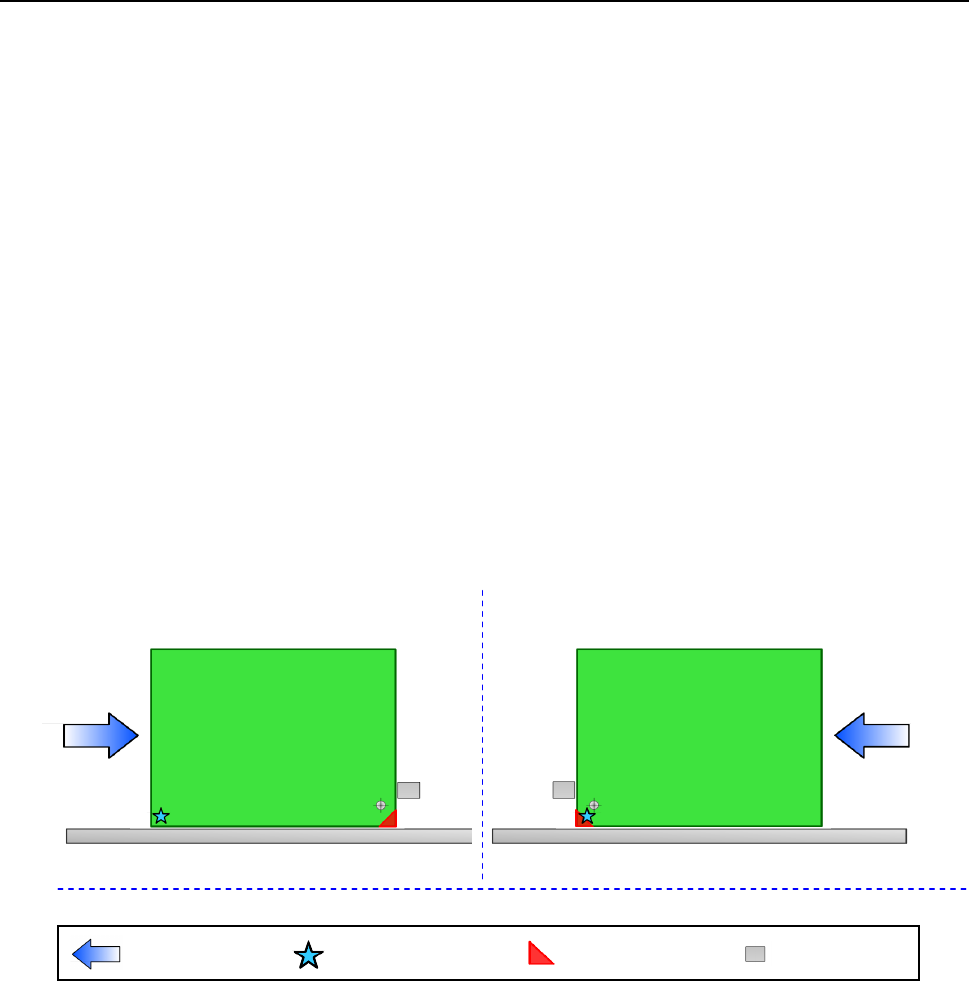
4.1.2.2.1 Reference
A PWB layout endpoint is defined according to the PWB transport reference side and
direction as shown in the figures below (in case of the edge reference position).
1) Front reference 2) Front reference
Transport direction: left to right Transport direction: right to left
Transport direction
Board reference position
(desired
position)
Board layout end point
Stopper
EPU Instruction Manual Chapter 4 Creating a Production Program
4-9
4.1.2.2.2 Dimension settings (single circuit PWB)
This selection specifies a PWB on which only one circuit is located.
(1) PWB dimensions
Enter the dimensions of a PWB here.
If the machine is supplied with a dummy PWB, enter the dimensions of this PWB
also.
The same direction as the PWB transport direction will be X and the vertical direction
to the PWB transport direction will be Y.
(2) Reference hole position
* Not used in JX-350.
Dimension X
Dimension Y