JX-350_EPU使用说明书.pdf - 第117页
EPU Instruction M anual C hapter 4 Creating a Production Progr am 4- 69 (6 ) Gri pper nozzle data 1) Grip position: Enter a neg ative value ( “-a” ) into the “ Y” field as t he offset f rom the center of a component to t…
EPU Instruction Manual Chapter 4 Creating a Production Program
4-68
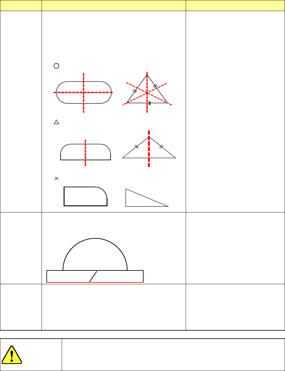
Comp Shape
Operation Applicable components
Flexible 2
From the measurement result, a left/right symmetrical
axis of the component is detected. From this axis, the
center coordinates and angle deviation amount of the
component are obtained and corrected for placement.
Regarding the component dimensions, the largest width
is judged as X/Y on the basis of the actual component
angle of 0° from the angle deviation amount
measured by the above calculation.
In the case of a component having
multiple symmetric axes, the center
coordinates of the component can be
accurately obtained. So, this shape
is very effective (example: “○”
component at left). In the case of a
single symmetric axis, the center
coordinates in X direction of the
component cannot be obtained
accurately, so that a placement
deviation may occur. (Example:
“△” component at left). However,
because this deviation amount has
reproducibility, it may be used if a
placement offset is entered.
In case the component has no
symmetry, this shape is not effective.
(Example: “x” component at left).
Flexible 3
The XY width deviation amount is calculated by using
the data close to the minimum with of the component.
The angle is calculated by the inclination of one side of
X direction of the component.
Odd-shape component
It is possible to recognize many
odd-shape components. However,
if the upper/lower part of the
component is round, the angle
deviation amount may be unstable.
(Because only one side can be used
to obtain the angle)
No Definition
The system rotates a component that is ready to be
picked up by the placement angle, and then places it
on a board.
Components that cannot be centered
with laser stably (extremely thin
components whose thickness does
not conform to the specifications):
the system places such a component
without centering it. Therefore, the
placement position is affected by the
pick-up position.
CAUTION
The initial setting of the “Comp Shape” is determined according to the
component type. Normally, if you change this initial value, an error may
occur more frequently. Never change the initial value except for the
special component.
(5) Nozzle display
The image, the outer dimensions, the applicable component size of a nozzle are
displayed here.
EPU Instruction Manual Chapter 4 Creating a Production Program
4-69
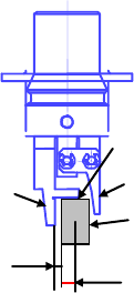
(6) Gripper nozzle data
1) Grip position:
Enter a negative value (“-a”) into the “Y” field as the offset from the center of
a component to the side against which a component is pushed (“a”). Do not
enter any value other than “0” into the “X” field.
2) Horizontal clearance:
Enter a negative value as the clearance between the side against which the
arm on the gripper nozzle fixed side is pushed and a component (“b”). Note
that the movement direction varies depending on the nozzle type and/or
nozzle direction.
Usually, set the default value that is automatically input.
3) Nozzle direction at picking:
Specify the nozzle direction when the nozzle picks up a component that is
supplied at 0 degrees. Specify one of the directions: 0, 90, 180 and 270
degrees.
4) Height adjustment:
Correction value (clearance between c and the top surface of the component)
Normally, set “- 0.5 mm” to keep a component horizontal.
Grip position (a)
Component
C
Fixed arm
Swing arm
Horizontal
clearance (b)
EPU Instruction Manual Chapter 4 Creating a Production Program
4-70
<Setting items when a gripper nozzle is used>
In addition to the items described above, you have to set the following items for a
gripper nozzle in the different way from those for other nozzles.
① When you use a new gripper nozzle, select the [File]/[Read Nzl. data] commands
on the “Machine setup” menu to load the information on the gripper nozzle from a
floppy disk first.
② Set the nozzle onto the ATC.
Attach the gripper nozzle onto the ATC so that the fixed arm of the gripper nozzle
can be located on the rear and the swing arm can be located on the front with
viewing the ATC unit from the front.
③ Specify the component data.
a. Set the nozzle number.
The numbers for gripper nozzles are from 800 to 899.
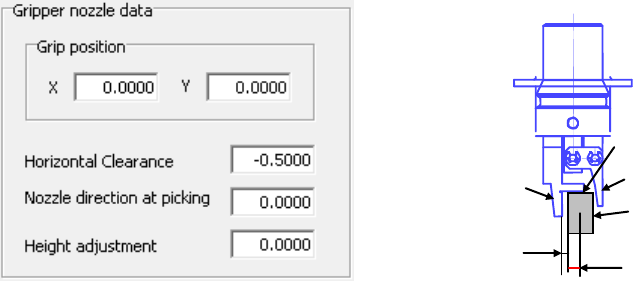
b. Set the laser position.
Specify the distance from the tip of the fixed arm to the laser position.
Guideline for setting the “Laser position”:
- (Component height - 3.5 mm*)/2
Make fine adjustments with based on the lead position.
* Distance from the “c” shown in the figure below to the fixed arm = 3.5 mm
Example: When the component height is 5 mm (5-3.5)/2 = - 0.75 mm
④ Set the pick data.
XY is the same as the ordinary teaching method. Regarding Z, its value is
automatically calculated from the nozzle information registered by machine setup
and the component height. So, no teaching is required.
Grip position (a)
Component
C
Fixed arm
Swing arm
Horizontal
clearance