JX-350_EPU使用说明书.pdf - 第64页
EPU Instruction M anual C hapter 4 Creating a Production Progr am 4- 16 4.1.2.2. 3 Dimension set tings (m ulti - ci rcuit PWB) W hen a PW B in which multiple same circuits are ar ranged on a single PW B is called “ mult …
EPU Instruction Manual Chapter 4 Creating a Production Program
4-15
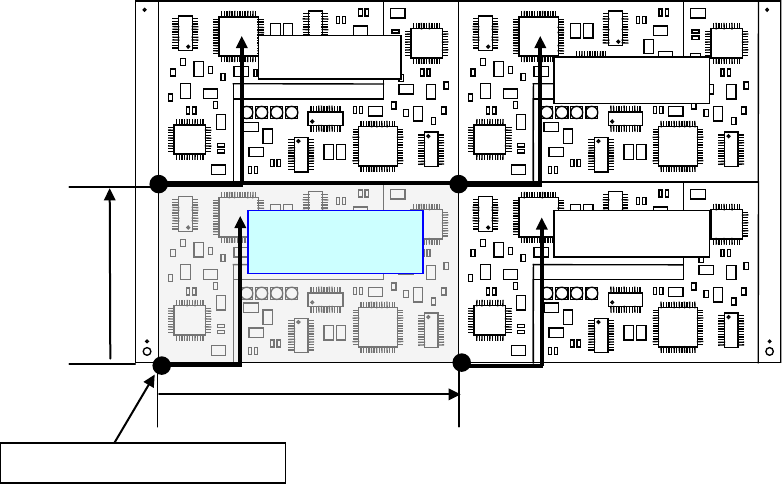
(12) Placement range every clamping
Enter a placement range at first clamp when clamping a large-shape PWB whose
PWB external size X exceeds 650 mm. When the number of components to be
placed is small, the tact may be improved by changing the placement range every
clamping.
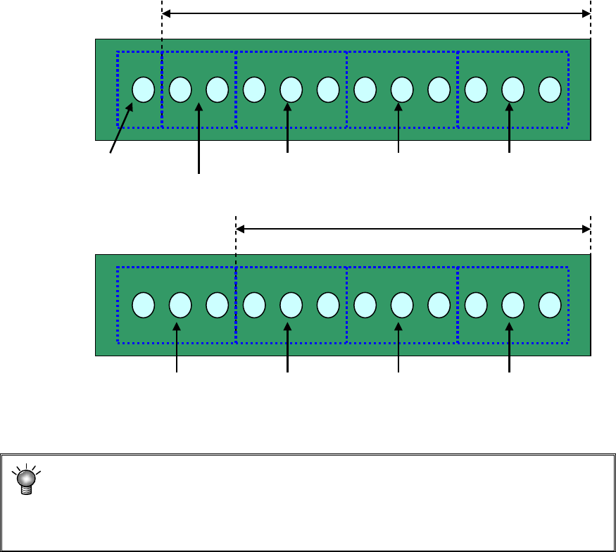
[Three components can be picked up at once.]
Adjusting the placement range every clamping will reduce the pickup count from 5 to
4. This greatly improves the tact.
* For using a large-shaped PWB whose external length X exceeds 1200mm
(option):
If the placement range at first clamp is changed from 650 (mm), a PWB range that
cannot be placed may occur. So, do not change this placement range.
Placement range at first clamp: 650 mm (initial value)
#1 Pickup/
placement
#2 Pickup/
placement
#3 Pickup/
placement
#4 Pickup/
placement
#5 Pickup/
placement
#1 Pickup/
placement
#2 Pickup/
placement
#3 Pickup/
placement
#4 Pickup/
placement
Placement range at first clamp: 550 mm
EPU Instruction Manual Chapter 4 Creating a Production Program
4-16
4.1.2.2.3 Dimension settings (multi-circuit PWB)
When a PWB in which multiple same circuits are arranged on a single PWB is called
“multi-circuit PWB.” As placement data, create the data for a single circuit (this circuit is
called “reference circuit”) and enter the circuit arrangement information (inter-circuit pitch,
number of circuits, etc.) into the PWB data.
Two types of multi-plane PWBs are available: matrix circuit board and non-matrix circuit
board
Second circuit
Fourth circuit
Pitch X
Pitch Y
Third circuit
Reference circuit
Origin of the reference circuit
EPU Instruction Manual Chapter 4 Creating a Production Program
4-17
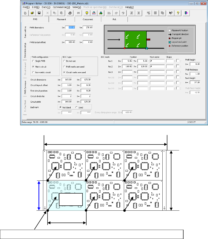
(1) Multi-plane matrix PWB
This is a PWB on which all circuits have the same orientation and the distance (pitch)
between circuits is equal.
Select the reference circuit (select a circuit at the left bottom, in general) among
circuits on a PWB.
Then, set the PWB origin and the circuit origin for placing the reference circuit and
enter the information of the number of circuits and the pitch between circuits.
By these data entries, the system places the specified number of circuits on a board
with based on the placement data of the reference circuit that is created on the
“Placement” data screen with shifting the position of each circuit by the specified
pitch.
PWB origin
of the reference circuit (normally, the PWB origin is equal to the circuit origin.)
Reference
circuit
PWB dimension X
PWB dimension Y
Circuit dimension X
Circuit dimension Y