JX-350_EPU使用说明书.pdf - 第123页
EPU Instruction M anual C hapter 4 Creating a Production Progr am 4- 75 ( 2) Pl a ce Offset XY Ө W hen the system centers a com ponent with laser , it holds the center of t he component based on t he outline of the compo…
EPU Instruction Manual Chapter 4 Creating a Production Program
4-74
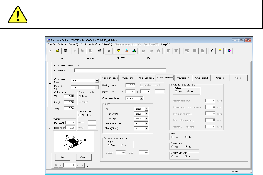
4.1.4.2.5 Place Condition
The placement conditions consist of setting items related to placement and default values
are applied. Accordingly, they do not need to be changed. If placement cannot be
performed normally in the default value status, change the settings.
CAUTION
If you change any of the basic settings after changing any value on the
“Place Condition” tab, some values are reset to their defaults on the
“Place Condition” tab.
(1) Placing stroke
Specify the distance for pushing a component to be placed from the top surface of a
board.
When you specify “0” in this field, a component may not reach a board due to the
flatness of the board and it may not be placed at the specified placement position
(that is, a placement error occurs), or a component may slide over the cream solder
when it is placed.
In such a case, increase the value set in this field so that a component can reach the
board (that is, enter a positive value).
The initial value is “0.5 mm” (0.2 mm for a 0603 chip component).
"The load is controlled" button becomes effective for the use of the nozzle with which
a simple load can be controlled after 601.
* Not used in JX-350.
EPU Instruction Manual Chapter 4 Creating a Production Program
4-75
(2) Place Offset XYӨ
When the system centers a component with laser, it holds the center of the
component based on the outline of the component observed with laser.
In CAD data or similar type of data, the center of the component-mounted pattern
(called “pad”) is regarded as the coordinates of the component placement position.
This difference may cause leads of a component to be shifted from the pad of a
PWB.
Therefore, when you enter this difference in this “Place Offset,” the system can place
a component at the correct position.
Example 1: One-direction lead connector
* Placement angle is 0°.
If the placement offset is not entered, components will be placed as shown below.
In the condition shown in the figure above (placement angle of 0º and placement
offset of 0), the system measures the distance from the coordinates of the component
placement position as the start point to the relative position of the component
placement position coordinates, and enters this distance into the “Place Offset” field.
To place two or more components of the same name, enter the placement offset in
this manner, and the placement position will be automatically changed and the
component will be placed on the correct position even if each placement angle is
other than 0°.
Placement offset -Y (X is 0)
Center position of a component
centered with laser
Placement coordinate
position
Top view of a component
Pad on a PWB
Pad on a PWB

EPU Instruction Manual Chapter 4 Creating a Production Program
4-76
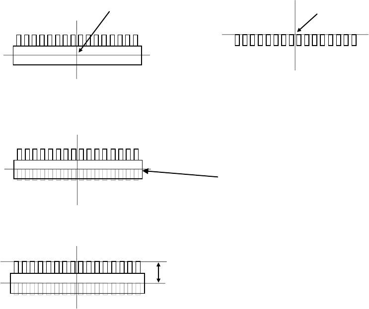
Example 2: Taking the following component as an example, enter the offset value. The
unit of numerical value is "mm (millimeter)."
( (no color) ⇒ Lead section, (colored) ⇒ Mold section, (bold line) ⇒ Pad)
Since the coordinates of the component placement position are different from the
center position of the component centered with laser, the system will not place a
component at the correct position. Therefore, enter this difference into the “Place
Offset” field as the offset value.
If any offset is not entered, components will be placed as shown below.
In this case, enter an offset value so that the tip of the lead will come on the center of
the pad.
If "X = -5.5, Y = -10" is entered in the "Place Offset" field, components will be placed
as shown below.
Coordinates of the component placement position
Laser height
Pad on a PWB
Top view of a component
Lateral view of a component
(from the front)
Center position of a component centered with laser
3
5.5
1
2
2
5
5
2