JX-350_EPU使用说明书.pdf - 第157页
EPU Instruction M anual C hapter 4 Creating a Production Progr am 4- 109 a) “ Show permanent nozzl e only ” check box: Checked: The system displays the nozzle lay out of t he A TC t hat is output with the “ O ptimizat io…
EPU Instruction Manual Chapter 4 Creating a Production Program
4-108
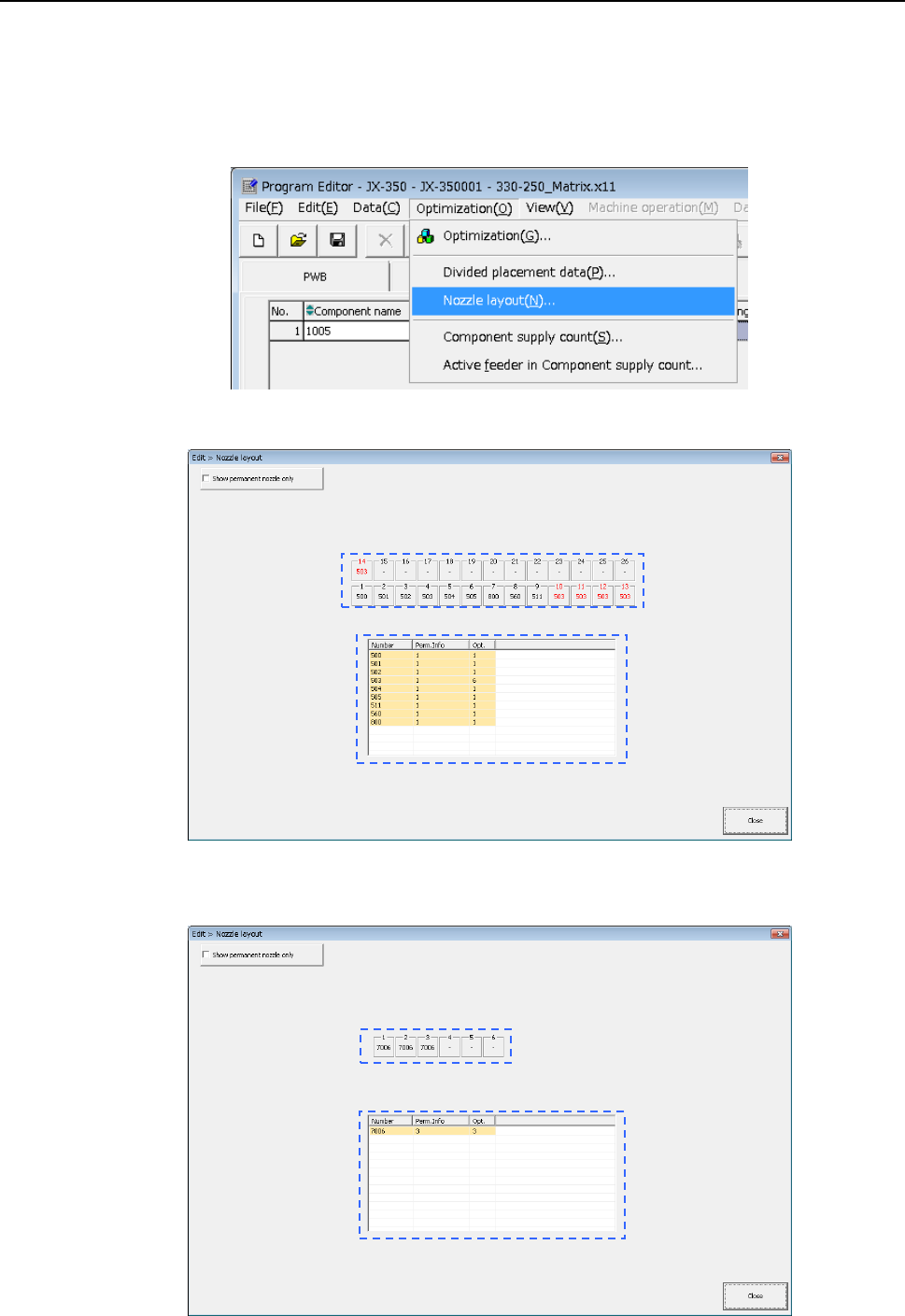
4.2.2.2 Nozzle layout
The [Nozzle layout] command displays the nozzles assigned to each station with the
Optimization function.
When you specify “Auto arrange nozzles” in the “Nozzles” field of the “Assignments”
option screen, check the result on the following screen, and set nozzles so that the
nozzles can be assigned in the same way specified on the “Machine setup” menu.
Select the [Optimization]/[Nozzle layout] commands from the menu.
The following “Nozzle layout” screen appears.
When the “Screw type nozzle” option in the “EPU setup” menu is enabled, the following
screen appears.
EPU Instruction Manual Chapter 4 Creating a Production Program
4-109
a) “Show permanent nozzle only” check box:
Checked: The system displays the nozzle layout of the ATC that is
output with the “Optimization” utility.
Not checked: The system displays the layout of the permanent nozzles only
that are set on the “EPU setup” screen.
b) Layout on the ATC display
Nozzle number displayed in red:
indicates a nozzle output with the Optimization function.
Nozzle number displayed in black:
indicates a permanent nozzle set on the “EPU setup” menu.
c) Number of nozzles
Ordinary status: Number of nozzles set by EPU setup.
Optimization: Required number of nozzles that is output by optimization.
EPU Instruction Manual Chapter 4 Creating a Production Program
4-110
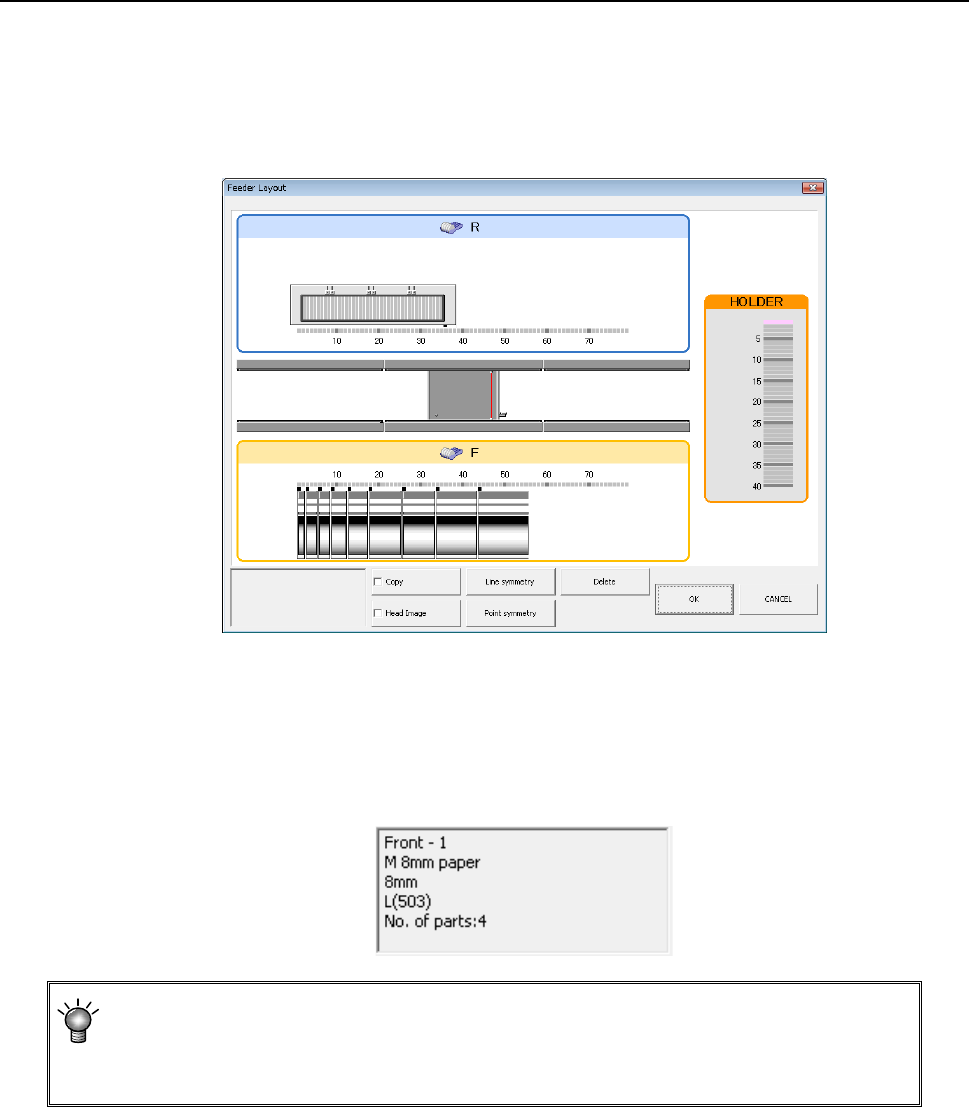
4.2.2.3 Feeder layout
The [Feeder layout] command displays the feeder layout specified on the “Pick” data
screen graphically.
When you click the [Display]/[Feeder layout] commands from the menu, the following
“Feeder layout” window appears on the screen.
(1) “Feeder layout” window
1) When you move the trackball over the figure of a feeder displayed on the “Feeder
layout” window, part of the Component data for the corresponding feeder is
displayed on the screen.
As the feeder information, a component pick-up position, a component supply unit,
a component name, a number of a nozzle used for picking up a component and
the quantity of components (when optimized) are displayed on the screen
All centering methods specified on the “Component” data screen appear as the
“Centering method (nozzle number).” Although the centering method (nozzle number)
that cannot be handled with a certain model appears on the screen, the Optimization
function assigns the centering methods (nozzle numbers) that can be handled with the
model.